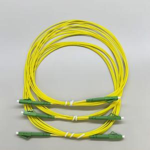
MTP MPO cables systems provide critical support for the modern information society by providing high-density multi-channel connectivity between data processing and distribution nodes. It is expected that in the next few years, with the development of 5G new radio technology and metro transmission networks, the number of connections utilizing MPO optical cable structures will increase significantly. Currently, LC-to-LC one-way and two-way connections are widely used due to their easy operation. However, for MTP MPO optical cable, its installation and use require users to have certain basic knowledge. The purpose of this article is to provide basic information about MPO-8, MPO-12 or MPO-16 – Key A or Key B – Type A or Type B – Trunk and Branch fiber optic cables in order to simplify the project planning, procurement and installation process. Achieve cost savings and efficiency improvements.
MTP MPO Cables
Nowadays, MTP MPO Cables are used interchangeably. However, they are not one and the same. MTP is an enhanced MPO cable version. Firstly, MTP connector has a removable housing that allows to polish, re-work and change connector heads. Secondly, it has a more advanced mechanical support system to ensure that cable is not easily broken inside the connector housing.
Nevertheless, many MPO has implemented similar mechanical support and provide breaking resistance from extensive bending force, but does not guarantee a removable housing.
Multi Fiber Push-On Connector
Best place to start is the connector as it is an easy way to distinguish the cable. There are many different types, for example, LC, SC, MT-RJ to name a few. MPO (Multi-Fiber Push On) connectors are semi-recent and widely used. However, demand and use for MPO will grow as more and more data lanes are required to keep up with 400G Ethernet demands.
100G SR4 in a QSFP28 form-factor MPO connector and a suitable MPO cable connector can be seen in the image below:
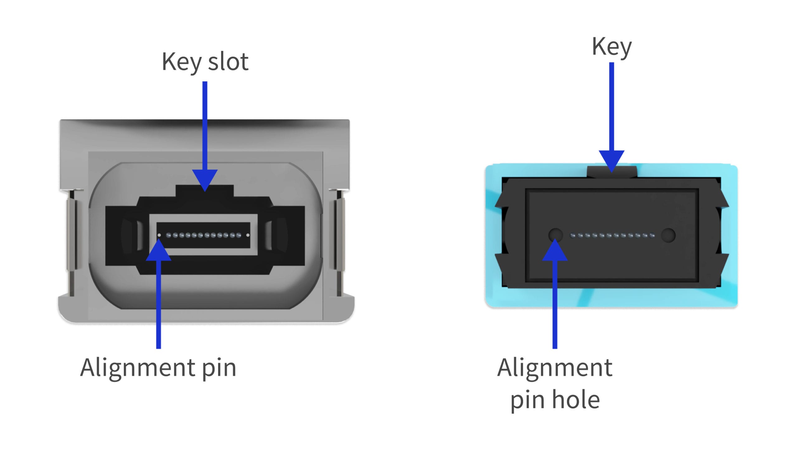
From the image it can be seen that there are several important points for choosing the correct MPO cable.
- Number of fibers/strands;
- Male or Female Connector;
- Keying, position of the key – Key Up or Key Down;
- Fiber-Polarity – Type A, Type B, Type C or Custom.
In the 100G SR4 QSFP28 example.
MPO cable has:
- 8 fibers/strands and utilizes an MPO-12 design [4 middle strands do not carry signal and are not used];
- Female Connector [no guide pins];
- Keying, position of the key, is Key Up.
- Fiber-Polarity is Type B, Reversed.
100G SR4 with QSFP28 form-factor has:,/p>
- 8 fibers/strands and utilizes an MPO-12 design [4 middle strands do not carry signal];
- Male Connector [has guide pins];
- Keying, position of the key is Up.
This is the most important paragraph for MPO – Transceiver connections and it must be remembered. MPO cable connector must be a Female to connect to a transceiver that has Male connector.
Male or Female Connector
It is common in electrical and electronics to refer to a connector by gender. This helps with faster navigation and helps to know which MTP MPO cable connector/head to use. To ensure a good and a firm connection, one side must be with Guide Pins and the other without them!
Male connectors are WITH Guide Pins.
Female connectors are WITHOUT Guide Pins.
Example of a MALE and and a FEMALE MPO cable connector can be seen in the image below:
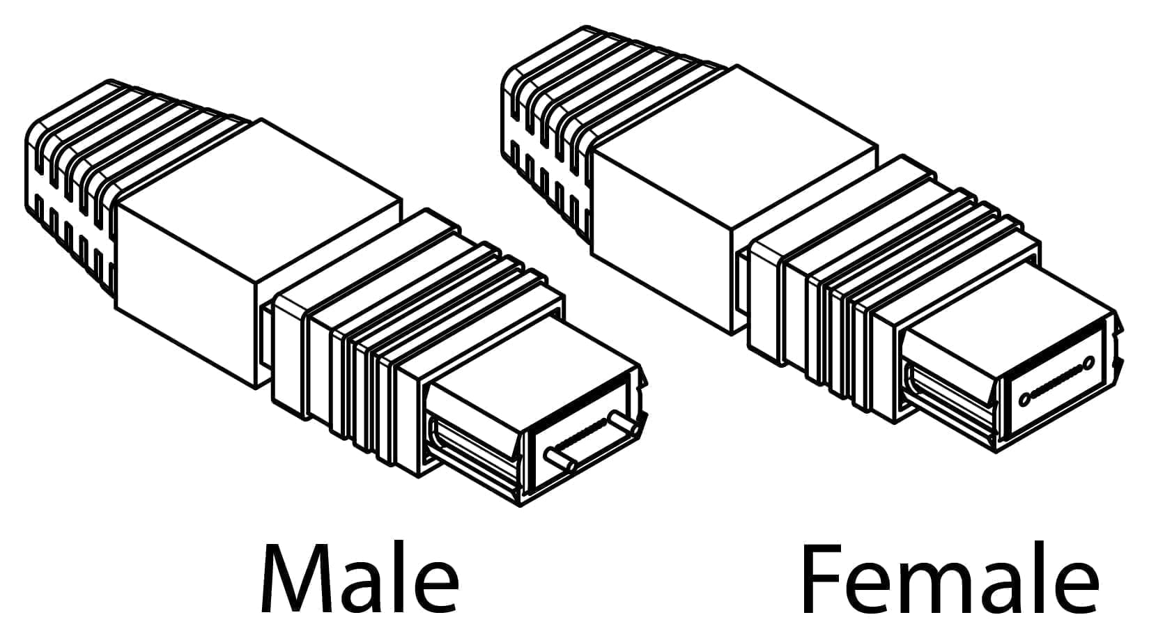
To reiterate, a Female connector is always connected to a Male connector.
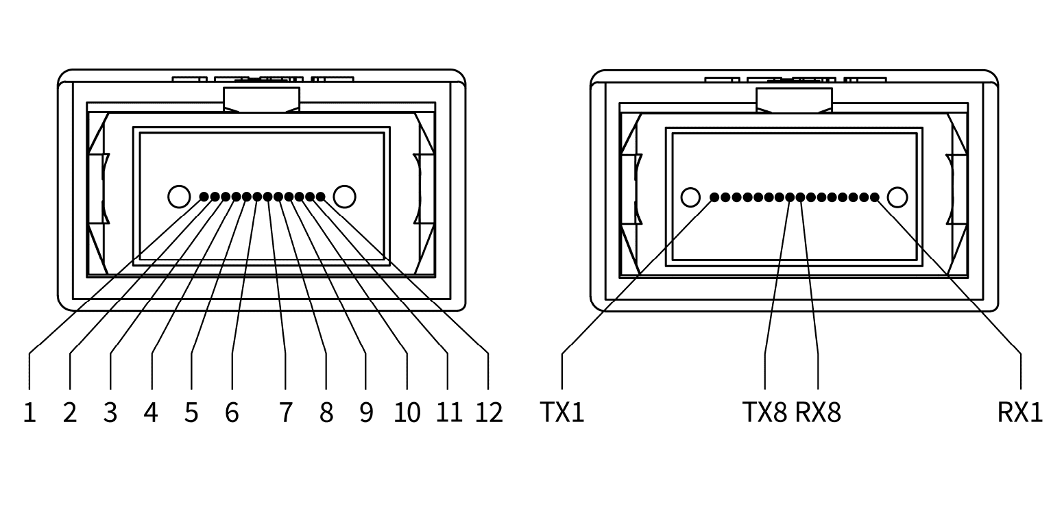
For Data Center Connections using 100G SR4 and 400G SR8 connecting MPO cable must be FEMALE due to QSFP28 and QSFP-DD modules having a built-in male connector/socket with guide pins. Examples of 100G SR4 on the left and 200G/400G SR8 on the right can be seen below:
Keying position – Key Up or Key Down
Next on the list, keying – a mechanical feature of a connector that guarantees a correct orientation of said connector. MPO and MTP connectors commonly have two ways of keying. Connector Key can be in UP or DOWN position. An example can be seen in the image below:
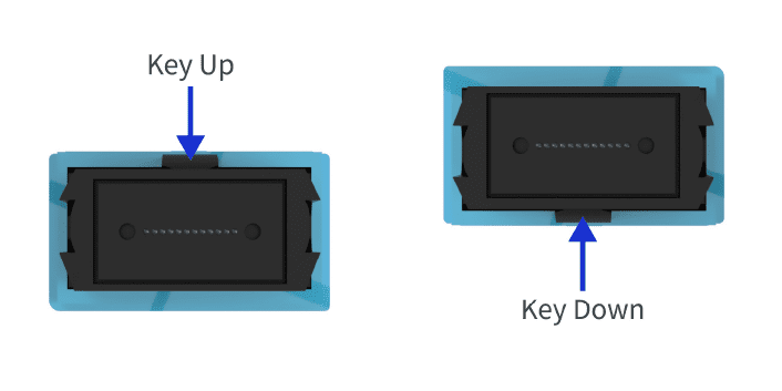
Position of the key have two important roles and ensures:
- Correct orientation to insert MPO cable into a socket;
- Ability to reference the exact Fiber/Strand that has to be inspected or spliced.
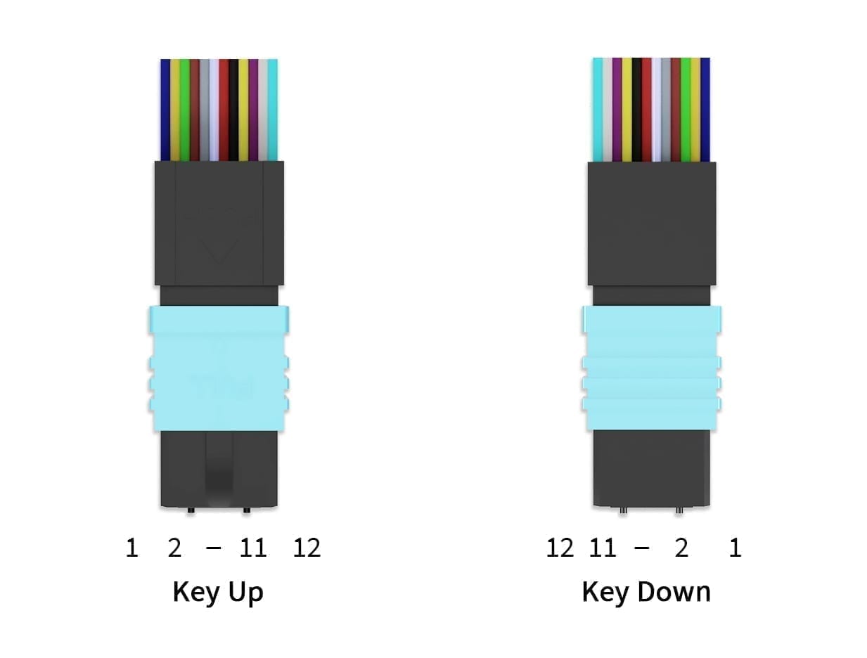
Specific fiber can be specified based on the position of the key. As each strand has a connection in the MPO connector a number can be given to it. The numbering starts from the Left to the Right Side of the Key. Examples for numbering for a MPO-12 with Key Up and Key Down are in the image below:
MTP/MPO Cable Number of fiber strands (12, 16, 24, 32, 48…)
A MTP MPO cables can have a different number of fibers/strands. Fibers are sorted in lanes of 12 or 16 and an example is provided below with MPO-12 on the LEFT and MPO-16 on the RIGHT
To reiterate, MPO-12 is the most common connector because of the wide spread 100G Ethernet connections that are used for almost all 100G SR4 connections and utilize 8 out of 12 available strands, where 4 lanes Transmit (Tx) and 4 lanes Receive (Rx) data signals. Nevertheless, with the development and introduction of 200G SR8 and 400G SR8 use of 16-strand (MPO-16) cables is required to establish and maintain connection over all 16 lanes.
It is important to know that these strands can be stacked in multiple rows to have, for example, 48, 72, 144-strand connections on a single MPO connector. That is why the same fiber numbering principle applies to connectors that have more than one row of fibers. Next line continues from the left where the previous one line stopped. Important – Lines are counted from bottom to top.
An easy way to know the number of the fiber – S = X*(R-1)+N, where
S is the fiber/strand order number,
X is the number of fibers in a single row,
R is the number of the row where fiber connection is positioned,
N is the position in the row.
Fiber Strand Color Code
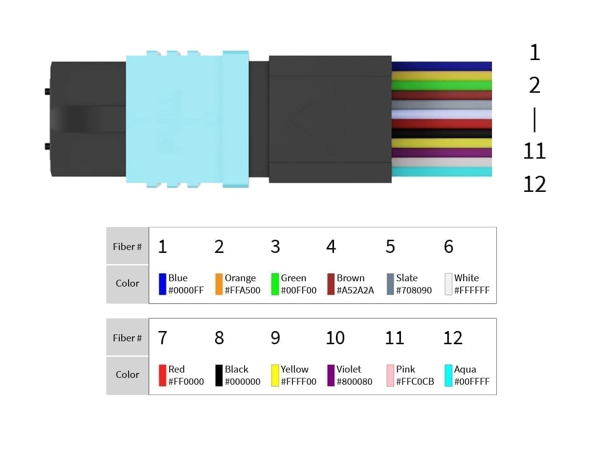
Another way to know the number of the fiber is the individual fiber jacket color code and is matching EIA/TIA-598 standard. This is especially useful for splicing when fiber has to be attached, repaired or removed. Example image is visible below:
MPO Fiber-Polarity Type
When it comes to Fiber-Polarity of MTP MPO cables, there are many possible customizable variations. However, only three that are widely used:
Type A – Straight:
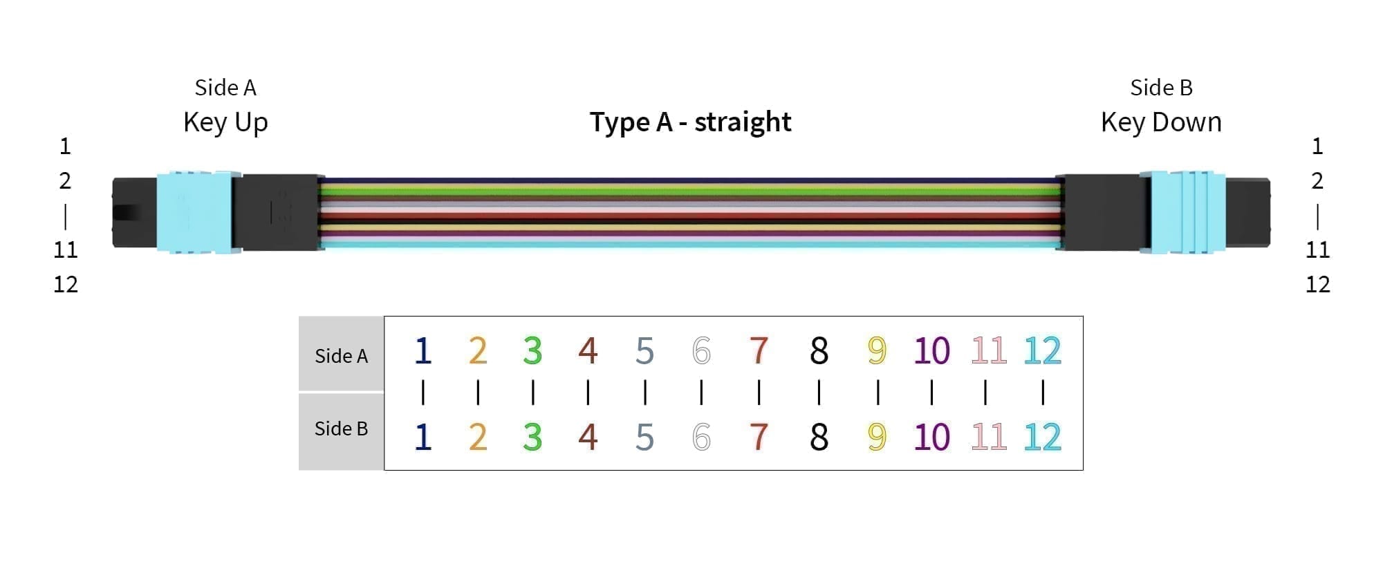
The Left (Key Up) side is connected to the Right (Key Down) side. Fiber #1 attached to position 1 on both sides. Same applies for Fibers #2, #3, …, #12:
Type B – Reversed:
The Left (Key Up) side is connected to the Right (Key Up) side. Fiber #1 attached to position 1 on the left and position 12 on the right. This can be written as Fiber #1 1-12. Same applies for Fibers #2 2-11, #3 3-10, …, #12 12-1.
Type C – Cross Pair:
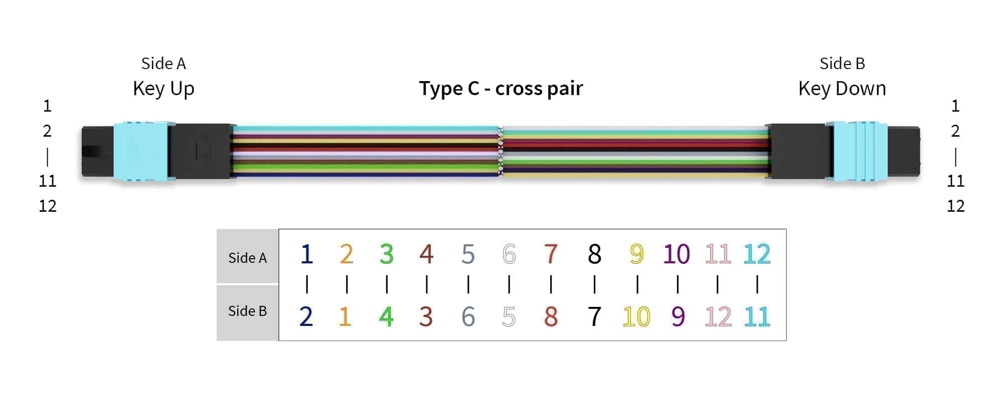
The Left (Key Up) side is connected to the Right (Key Down) side. Fiber #1 attached to position 1 on the left and position 2 on the right. Fiber #2 attached to position 2 on the left and position 1 on the right. This can be written as Fiber #1 1-2, Fiber #2 2-1. Same applies for Fibers #3 3-4, #4 4-3, …, #12 12-11.
Type A and Type B are the most common to establish a working link. Type is chosen based on requirements and/or project.
Nevertheless, Type B (Reversed) is the go to option for 100G SR4, 200G SR8 and 400G SR8 connections. Reversed Fiber-Polarity connection ensures that Transmission (Tx) channels are aligned with Receiver (Rx) channels.
When Fiber/Strand Count, Connector Keying and Fiber-Polarity Type is known, correct Tx -> Rx and Rx <- Tx connection can be assured. This is similar for smartphones utilizing Micro-USB – one way works it charges and the other way does not charge. However, it is important to know what wavelength is used to make a correct choice between Single-Mode Fiber and Multimode Fiber.
MPO Jacket Color
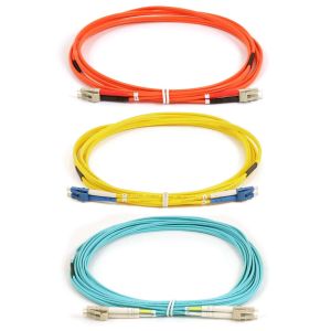
MTP MPO Cables can have multiple Jacket colors – Yellow, Blue, Violet, Green, etc. This is because it is an easy way to understand and to distinguish cable’s mode and features. For example, Yellow jacket shows that cable has a Single-Mode Fiber, SMF for short, and Aqua jacket shows that cable has a Multimode Fiber, MMF for short. Jacket Color Table shows most used equipment cable category and corresponding color.

On a side note. Each SMF and MMF has their advantages and drawbacks. The main being the supported distance. MMF cables are mostly used for short distance connections at ranges from 5 to 300 meters and can utilize cheaper transceiver and receiver components. SMF cables are and can be used for all ranges, starting from 1 meter to several thousands kilometers but require more precise and expensive lasers and diodes.
MPO Trunk Cables
MPO Trunk cable is a way to consolidate and provide compact cross-connection across the infrastructure. They are widely used in campus, telecom, data center and corporate networks. Furthermore, MPO Trunk, it cannot be said enough, cables provide exceptionally high density and high quality transmission performance and have a very low signal loss.
When thinking of MPO Trunk cables, think of 1:1 connections where both sides are 40G, 100G, 200G, 400G or even 800G. What comes in on one single end will come out on the other single end. To ensure a good connection, it is required to match Trunk Cable fiber count to that of the Transceiver or other Equipment on both ends. Below MPO Cable to Transceiver table shows the relation of transceiver Transmission lane count and required Fiber count. It is preferred to use short abbreviations to name Short Range (SR) and Long Range (LR) transceivers. After corresponding SR or LR a number is added, this matches the number of Transmission (Tx) lanes [in some cases Receiving (Rx) lanes]. For example, 100G SR4 is a 100G transceiver utilizing 4 lanes each capable of 25G data rate for Tx. The same amount of lanes are required for Rx also. To ensure 100G SR4 to 100G SR4 connection there is a need for 4 Tx lanes and 4x Rx lanes which requires a total of 8 lanes. However, MPO-8 is not used. Transceivers that require MPO-8 use MPO-12 and are developed to be fitted with it.
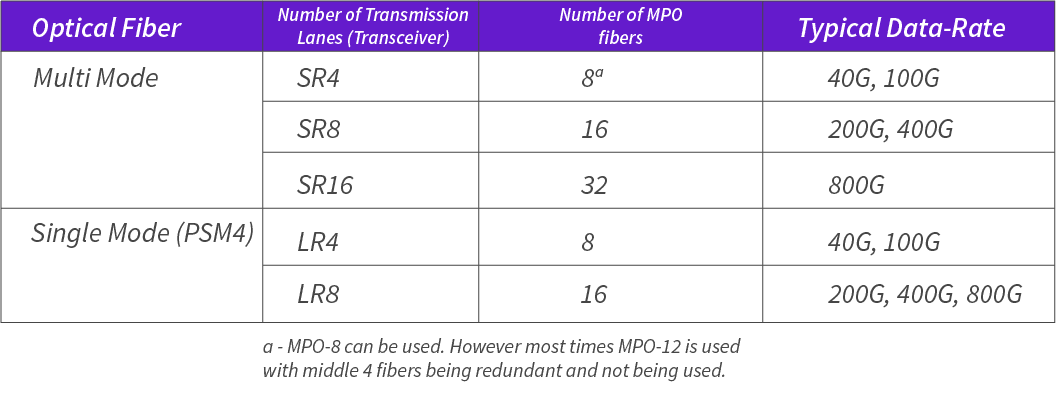
Additionally, below are the schematics and pinouts for the most common MPO Trunk Cables. More information regarding ordering this can be found in our MTP-MPO cable product page.
Trunk Cable schematic/structure images and pinouts
MPO-8 in a MPO-12:


MPO-24:

MPO Break-Out Cables
MPO Break-out cables are excellent for splitting and merging data flow. Most common conversion is the MPO to 4 LC. To add to this, 1 to 4 conversion is excellent for 40G to 4x10G and 100G to 4x25G conversion as both can use the same MPO breakout cable. However, not all 40G and 100G transceivers are capable of this conversion as it requires a built-in MPO connector and it comes only in SR4 (Short Range 4 lane) and PSM4 (Parallel Single Mode 4 lane) transceiver versions. More on transceiver types can be read in our 100G-QSFP28 transceiver article. In short they have these characteristics:
- SR4 operates at 850nm wavelength and requires OM4, OM5 cable that comes in Aqua, Violet or Lime Green jacket colors.
- PSM4 operates at 1310nm wavelength and requires OS2 cable that comes in Yellow jacket color.
To add to the power of MPO Break-out cables, 1 to 8 conversion is becoming more popular. Where a 200G SR8 or 400G SR8 is utilized at one end and at the other end a data rate matching 25G SFP28 or 50G PAM SFP56 is being used. This adds to the simplifying of topology by reducing the total number of equipment needed to convert from high to low data rate.
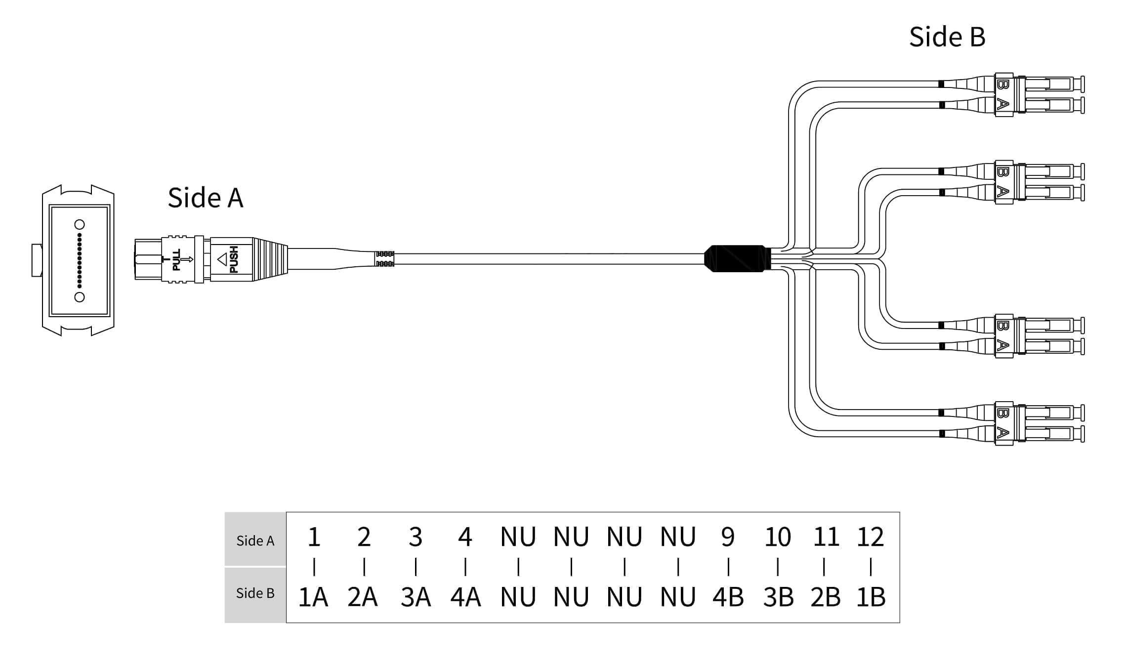
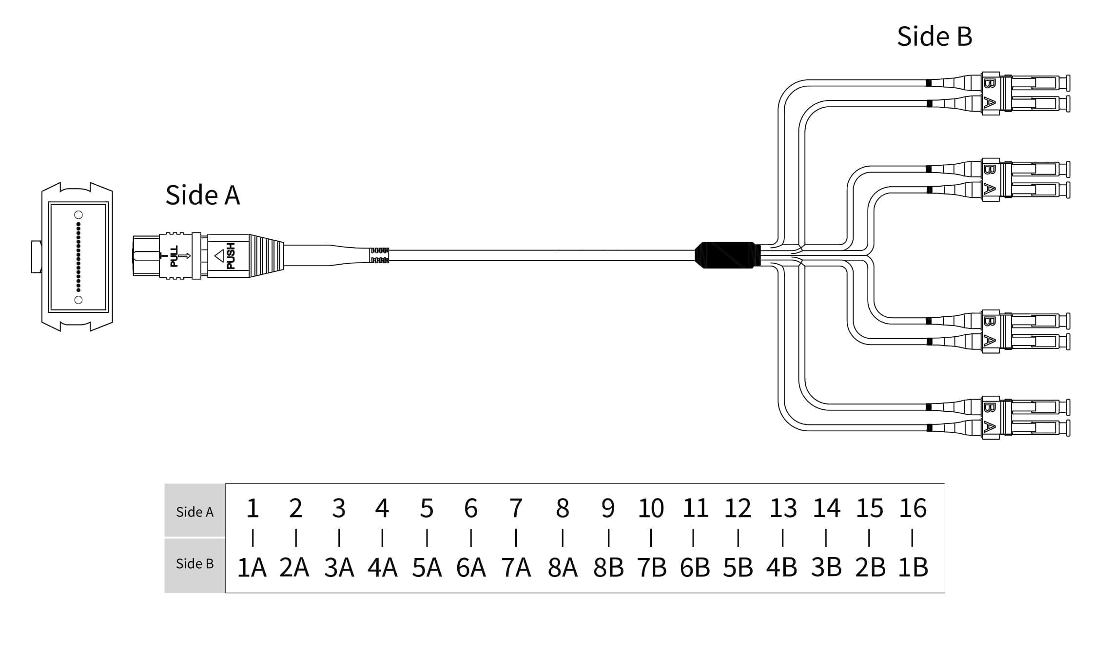
Below are schematic and pinout of both MPO-12-4LC and MPO-16-8LC. More information regarding the possibility to order these products can be found in our MTP breakout product page.
MPO-12-4LC:
MPO-16-8LC:
Loose Tube and Ribbon Fiber Cable
As a fun side note, MPO and other multiple strand optical cables can be made in Loose Tube and Ribbon Fiber forms:
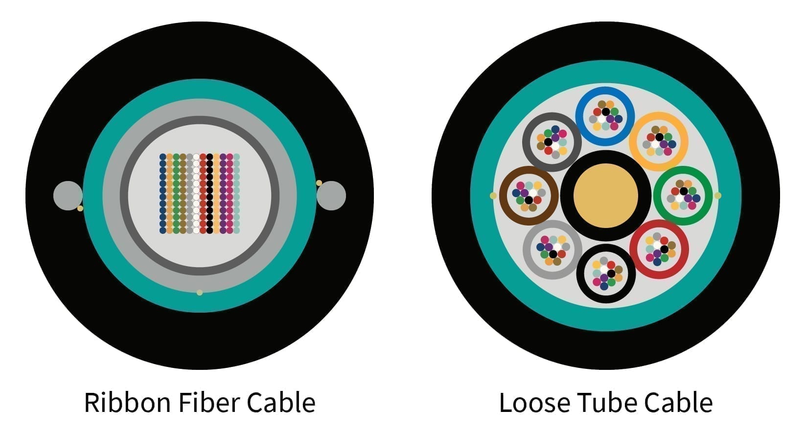
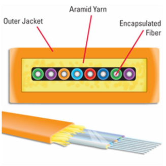
Loose Tube cables are the usual MPO cables seen. A thick cable with a high amount of cladding material. This is used for industrial applications and areas where cable can experience an outside influence. Ribbon Fiber cables, in contrast, are thin and use less cladding. This allows for greater fiber density over the same cable run. The drawback is the fragility of the ribbon. It must be installed securely and protected from outside influence.
To re-iterate industry standard MPO-12 and MPO-16 cables are Loose Tube cables to work in 95% of use cases. However, Ribbon Fiber cable MPO-12 and MPO-16 are also available and can be supplied on an per agreement basis.
Have a suggestions, questions or comments – please, Contact Us!

