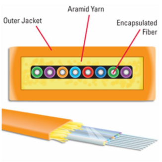
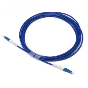
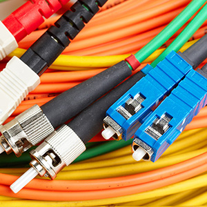
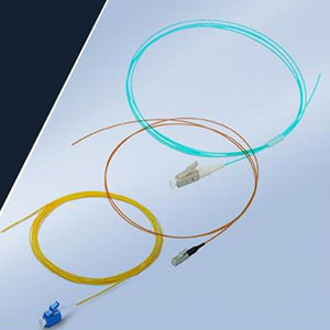
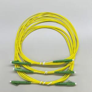
In the not-so-distant past, network security and connectivity were straightforward, relying on firewalls and copper cabling with the ubiquitous RJ45 connector. While copper remains a fixture in data centers, the undeniable rise of fiber optics cannot be overlooked, even by the staunchest copper supporters.
Understanding fiber modes and cable specifications may seem daunting, but grasping a few key fiber facts is crucial before you plan your network’s connectivity and visibility fabric. Here are the essentials: the distinction between single-mode and multi-mode fiber, an explanation of fiber wavelengths, and the concept of the light loss budget.

Single-mode vs. Multi-mode Fiber
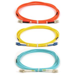
Fiber cabling isn’t as straightforward as copper; it’s divided into single-mode and multi-mode before you even consider the required speed. Single-mode fiber, though pricier than multi-mode, offers a superior performance that goes beyond cost considerations. The key lies in attenuation—the signal loss due to distance traveled through the cable, measured in decibels (dB).
Single-mode fiber boasts significantly lower dB loss, justifying its higher cost. Its slender 9-micron core diameter reduces reflections and, consequently, attenuation, making it ideal for long-distance, high-speed connectivity.
In contrast, multi-mode fiber cables feature either a 50-micron or 62.5-micron core, offering minimal attenuation over short distances. However, the larger core size leads to increased reflections and signal loss over longer distances.
Fiber Wavelengths and Their Impact on Attenuation
Three primary wavelengths dominate fiber optic communications: 850 nm and 1300 nm for multi-mode, and 1550 nm for single-mode (with 1310 nm as a less common single-mode option). These wavelengths are chosen for their minimal absorption, which occurs when water vapor in the glass increases attenuation.
Scattering, the reflection of light off glass atoms, is more pronounced at shorter wavelengths like 850 nm but diminishes as the wavelength lengthens. This is why single-mode fiber at 1550 nm experiences less attenuation and provides superior signal quality over long distances.
Considering Fiber Light Loss in a Passive Optical Network (PON)
Every PON has a loss budget, dictating the theoretical amount of signal loss the network should endure. This budget guides your choice of cables and links and serves as a benchmark for proper cable installation.
Be cautious with light loss budgets, as the lack of industry standards allows manufacturers to exaggerate their products’ performance. Focus on measuring fiber optic light loss in three key areas: through splitters, and as detailed in Jerry Dillard’s technical paper on “Loss Through Fiber Optic TAPs.”
Beyond the Basics of Network Connectivity
While these topics form the foundation of fiber knowledge for modern network architects, the conversation around network connectivity extends far beyond. Previous discussions have complemented these fiber facts, covering topics such as media conversion, the transition from 10G to 40G, avoiding fiber pitfalls, and making 40G fiber more accessible through Cisco BiDi technology.
For those looking to integrate fiber TAPs into their next deployment, our team offers a no-obligation network Design-IT consultation or demo. It’s an opportunity to delve deeper into the world of network connectivity—something we’re passionate about us.

