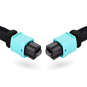
Fiber optic connectors were once bulky and difficult to handle. With the standardization and simplification efforts by manufacturers, today’s fiber optic connectors offer superior performance and are much more user-friendly. This increased ease of use has driven the adoption of fiber optic systems. This tutorial will provide a brief analysis of the current fiber optic connectors market and a detailed introduction to Fiber optic connectors.
A Brief Analysis of the Fiber Optic Connectors Market
In recent years, the global market has been propelled by the growing adoption of fiber optic technology. Fiber optic cables are increasingly replacing copper cables, positively impacting the fiber optic connector market. The following bar chart from Grand View Research illustrates the development of fiber optic connectors types such as LC, SC, and MTP in recent years.
Fiber Optic Connector Market
The chart clearly shows a steady growth trend for these five commonly-used fiber optic connectors. Specifically, LC connectors are expected to continue dominating the primary optical connector market for the next few years, while the demand for MTP/MPO connectors is also rising, suggesting that they may capture a larger market share.
In conclusion, the overall growth trends reflect a consistent demand for fiber connectors. The market is witnessing the development of fiber optic connectors. High-density and high-quality connectors like LC remain the top choice for many users. Multi-fiber optical connectors, such as MTP/MPO and even Rosenberger Q-RMC connectors, may gain more popularity due to the widespread deployment of high-bandwidth 100G/200G/400G networks and 5G applications. We can anticipate that, with the growing demand for efficient cabling and cable management, fiber optic connectors that offer easy installation, low fiber loss, and high performance will continue to set the trend in optical communications.
Fiber Optic Connectors Archives
What is a Fiber Optic Connectors?
A fiber optic connectors, also known as an optical fiber connector, is a component that terminates the end of a fiber optic cable, enabling quicker connections and disconnections than fiber splicing. It mechanically couples and aligns the fiber cores to ensure successful light transmission. Therefore, fiber optic connectors significantly impact the reliability of fiber optic transmission and the performance of the system. Generally, high-quality optical connectors will lose minimal light due to fiber reflection or misalignment.
Standards for Fiber Optic Connectors
As an optical component, fiber optic connectors adhere to several standards in the fields of telecommunications cabling and electrical engineering.
| TIA/EIA | Telcordia | IEEE |
|---|---|---|
| TIA/EIA-4750000-B: Generic Specification for Fiber Optic Connectors | GR-326: Generic Requirements for Single Mode Optical Fiber Connectors | IEEE Ethernet protocol standard 802.3: for Carrier Sense Multiple Access with Collision Detection (CSMA/CD) Access Method and Physical Layer Specifications |
| TIA/EIA-604: Fiber Optic Connector Intermateability Standards (FOCIS) | GR-1435: Generic Requirements for Multi-fiber Optical Connectors | IEEE standard 802.3ae: for 10 Gigabit Ethernet over Optical Fiber (single mode and multimode) |
| TIA/EIA-568-B.3/C.0/C.3: Commercial Building Fiber Optic Standards | / | IEEE standard 802.3aq: for 10 Gigabit Ethernet over Installed Multimode Optical Fiber up |
What is the Structure of Fiber Optic Connectors?
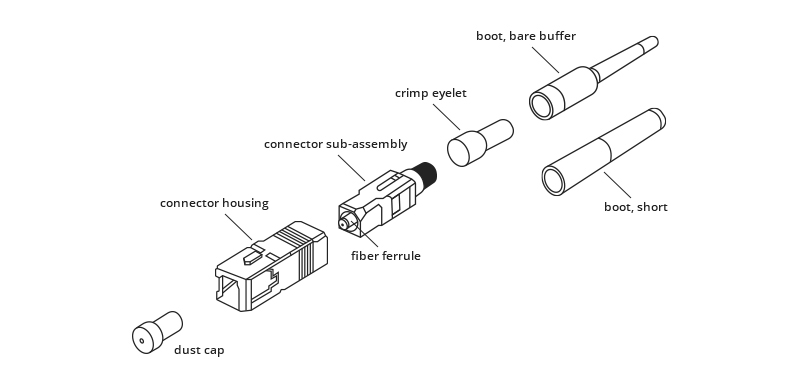
In the design of an optical connector, there are five key components: the fiber ferrule, the sub-assembly body, the connector housing, the fiber cable, and the stress relief boot. We will use the SC connector as an example to illustrate the structure of a fiber optic connectors.
Fiber Ferrule
The SC fiber optic connectors is built around a long cylindrical ferrule with a diameter of 2.5mm, made of ceramic (zirconia) or metal (stainless alloy). A high-precision hole with a diameter of 124um to 127um is drilled in the center of the ferrule, where the stripped bare fiber is inserted and typically bonded with epoxy or adhesive. The end of the fiber is polished smooth at the end of the ferrule.
Sub-assembly Body
The ferrule is assembled into the SC sub-assembly body, which has mechanisms to hold the cable and fiber in place. The end of the ferrule protrudes from the sub-assembly body to mate with another SC connector inside a mating sleeve, such as an adapter or coupler.
Connector Housing
The fiber optic connectors housing then covers the connector sub-assembly body, providing the mechanism for snapping into a mating sleeve (adapter) and securing the connector in place.
Fiber Cable
The fiber cable and strength member (aramid yarn or Kevlar) are crimped onto the connector sub-assembly body with a crimp eyelet, increasing the mechanical handling strength of the connector while also protecting the fiber inside.
Stress Relief Boot
The stress relief boot covers the joint between the connector body and the fiber cable to protect the fiber cable from mechanical damage. The design of the stress relief boot varies for 900um tight-buffered fiber and 1.6mm to 3mm fiber cables.
Key Features of Fiber Optic Connectors
The key characteristics of fiber connectors include optical properties, interchangeability, repeatability, reliability, and insertion cycles.
Optical Properties: Insertion loss and return loss are the two main parameters for optical properties. The lower the insertion loss value, the better. Typically, a qualified connector should maintain an insertion loss value below 0.5dB. Conversely, a higher return loss indicates better connector performance. The typical value for a connector’s return loss should not be less than 25dB, and practically, it should not be less than 45dB due to the polishing process.
Interchangeability and Repeatability: Fiber optic connectors are universal passive devices. Connectors of the same type can be used in any combination and can be reused.
High Reliability: Outdoor applications may require fiber connectors to be located underground or on outdoor walls. High-reliability fiber connectors are necessary in these harsh environments to ensure smooth optical transmission.
Utilization Rate: Generally, connectors can be plugged more than 1,000 times. Therefore, an easy-to-use fiber connector will help users save a lot of installation time and improve work efficiency.
Fiber Optic Connectors Types
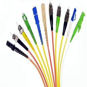
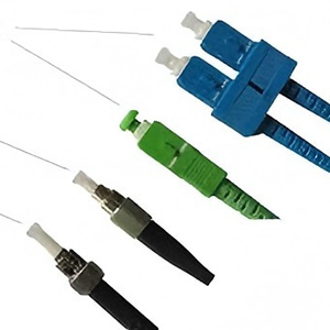
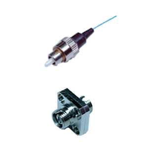
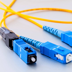
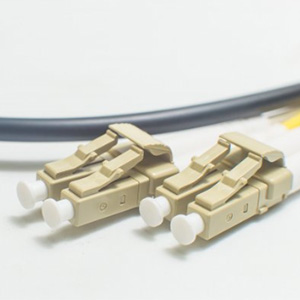
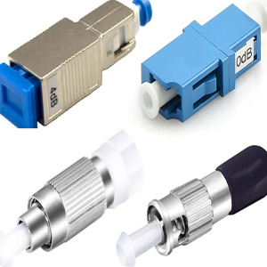
Based on different classification methods, fiber optic connectors can be divided into various types. According to the pin end surface of the connector, they can be categorized into PC, UPC, and APC. Based on the different transmission media, fiber connectors can be divided into single-mode and multimode fiber optic connectors. Multiple fiber optic connectors have been introduced to the market, but only a few represent the majority, such as LC, SC, FC, ST, and MTP/MPO connectors.

The aforementioned optical connector types are common fiber optic connectors that require an adapter panel for connection and are widely used in data centers, telecom rooms, server farms, cloud storage networks, and more. However, the two new and robust industrial connectors from Rosenberger, namely Q-RMC and NEX10 fiber optic connectors, feature a Push-pull Quick Lock design for easy installation. Both Q-RMC and NEX10 connectors are designed for harsh environments and are recommended for use in industrial sites, mine fields, mobile communication (FTTA), 5G base stations, and similar applications.
Fiber Optic Connectors Coupling Loss
Only the light that is coupled into the receiving fiber’s core will propagate, while the rest of the light is not transmitted through the splice and is radiated out of the fiber. Ideally, the loss is minimized if the two fiber cores are identical and perfectly aligned, the connectors or splices are properly finished, and no dirt is present. Unfortunately, both the fiber and connector are subject to manufacturing tolerances that result in less than perfect alignment.
Connector and splice loss is caused by many factors. For example, end gaps affect insertion loss and return loss. Therefore, optical connectors adopt various polishing techniques to ensure physical contact of the fiber ends to minimize back reflection. Additionally, light from a fiber with a larger numerical aperture (NA) is more sensitive to angularity and end gap, so transmission from a fiber of larger NA to one of smaller NA will result in higher loss than the reverse. In other words, connecting larger fibers to smaller ones results in substantial losses, not only due to the smaller core size but also the smaller NA of most small-core fibers.
Fiber Optic Connectors Applications
Fundamentally, fiber optic cables with optical connectors are primarily used in the field of telecommunications, from small or medium-sized offices to hyper-scale data centers. As shown in the following figure, telecommunications account for the largest market share in terms of revenue. Moreover, the increasing demand for 5G networks, 100/200/400G high-speed transmission, and cloud-based applications will also stimulate demand. There is a continued rise in global demand from the burgeoning IT industry for power-efficient, cost-effective, and high-level network infrastructure.
Additionally, the oil & gas, military & aerospace, and medical application segments are expected to witness significant growth rates due to the increasing adoption of multimode and Plastic Optical Fiber (POF) across these segments. For instance, military forces use optical connector technology for a wide range of ground, sea, air, and space applications, such as in avionics testing equipment modules and ground support systems for fighter planes.
FAQs
For 125um fibers, should I choose a 125.5um or 126um hole ferrule? What’s the difference?
The 126um hole is the recommended ferrule size for 125um single-mode fiber. Some 125.5um ferrules are available for critical alignment situations, but the 126um hole allows for some epoxy bonding around the fiber for insertion without breakage.
How are fiber connectors tested?
Typically, testing is divided into two parts: field testing and factory testing. Factory testing may use a profiling system to ensure the correctness of the overall polished shape of the fiber optic connectors. An optical microscope may be used to observe blemishes. Field testing involves the use of a special hand-held optical microscope for checking dirt and blemishes, as well as certain other tests to examine the parameters.
How to choose a proper fiber connector?
Fiber patch cables can be purchased in different configurations (SC-SC, SC-LC, etc.). The type of equipment you are installing will determine the requirements for your fiber optic connectors.


