The LC fiber cable, once a staple in enterprise deployments, has undergone significant transformations over the past two decades. Originally designed for straightforward installations, it now faces the challenges of high-density data center environments. This evolution has necessitated adjustments to its design, enhancing its utility in modern, complex installations.
Content:
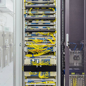
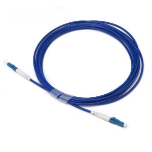
The LC fiber cable, in its current form, is a far cry from its initial incarnation when it was first introduced to enterprises over twenty years ago. The demand for fiber cabling has surged, particularly in data centers, where it forms the backbone of vast office parks and business campuses. These installations often culminate in buildings, where the cables connect to the data core and terminate in a fiber enclosure. The LC connector, favored for its compact size and ease of use, mirrors the ubiquitous RJ-45 used in copper connectivity. However, the sheer volume of fiber cables in modern installations can lead to congestion within these enclosures. For instance, a 576-strand fiber cable bundle, terminated with LC connectors, would require a staggering 288 LC connectors. This density poses a challenge for the traditional LC fiber cable assembly, prompting a need for innovation.
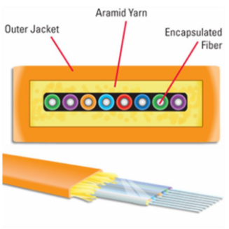
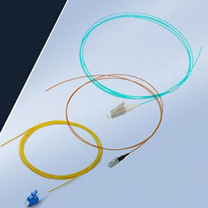
In the past, a traditional LC fiber cable assembly featured long strain-relief boots and a bulky 3-mm zip wire, with each fiber encased in its own protective jacket. This design was adequate when density was not a concern. However, in today’s high-density installations, this approach is no longer practical. To address these challenges, several modifications have been made to the standard LC fiber cable assembly:
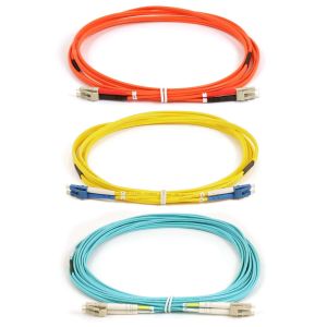
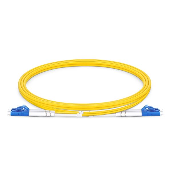
- Smaller O.D. Jackets: Initially, fiber assemblies utilized two 3.0-mm individual jacket fiber strands. Recognizing the need for space efficiency, manufacturers have reduced the jacket size to 2.0-mm, resulting in a significant 55% reduction in space consumption.
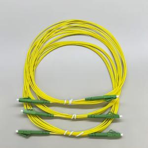
- Uni-Boot Jacket Design: Abandoning the traditional “Zip Cord” layout, the “Uni Boot” jacket design consolidates each TX and RX fiber into a single common jacket, further reducing space by an additional 50%.
- Addition of Pull Tabs: With fiber installation densities reaching up to 144 fibers (72 LCs) in a 1 RU space, accessing and replacing a buried LC connector can be daunting. To facilitate easier removal and installation, a “Pull Tab” has been added to the LC connector, enabling users to pull the tab to release the latch and remove the connector.
- Labeling: Enhanced labeling has been implemented to improve visibility and organization within dense installations.
- Bend Insensitive Fiber: This feature ensures that the fiber cable maintains its performance even when subjected to bending, crucial for installations where space constraints might lead to bending.
- Smaller Strain Relief Boots: These boots are designed to protect the fiber while occupying less space, further contributing to the compact nature of the assembly.
- Reverse Polarity Option: This option allows for flexibility in installations where specific configurations are required.
The LC fiber cable, with its numerous enhancements, has evolved to meet the demands of high-density, high-bandwidth applications prevalent in today’s data centers. The combination of smaller cable jackets, uni-boot jacket design, pull tabs, improved labeling, bend insensitive fibers, smaller boots, and reverse polarity options are essential for modern installations.