OTDR (Optical Time Domain Reflectometer) is a commonly used test equipment in fiber optic communications, which can help detect the loss, fault points and other performance indicators of fiber optic lines. For fiber optic engineers and technicians, mastering the use of OTDR Tester is the key to ensuring the stable operation of fiber optic networks. In order to let everyone understand the operation methods and applications of OTDR Tester more intuitively, we have carefully prepared this illustrated tutorial to guide you step by step to master the basic operation and common testing techniques of OTDR Tester. Whether you are a novice or an experienced practitioner, this article will provide you with a clear operation guide to help you quickly get started with OTDR Tester and improve your work efficiency.
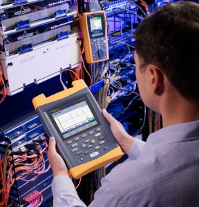
The OTDR Tester can be used to measure fiber length and event locations, fiber attenuation and distribution, the actual loss of fiber joints, and the total return loss of fiber. Taking the measurement of fiber distance as an example, the length measurement is primarily based on the time interval at which the laser encounters a fault point after entering the fiber, which is then reflected back to the OTDR Tester. This article will use the KL-6200 backbone engineering machine as an example to introduce the practical operation process of the OTDR.
I. OTDR Tester Key Operation Methods
- Press the SHIFT key to switch the curve zoom mode.
- Use the left and right Tab keys to switch between pages and setting tabs.
- The OTDR Tester start detection key.
- The ENTER key is used for navigation and changing settings.
- The navigation keys are for cursor movement and setting adjustments.
- The power on/off key (long press) / illumination key (short press).
- File management key.
- Red light source on/off key.
- Cancel/return key.
II. Curve Interface Structure and Meaning
- The curve page displays the OTDR Tester curve, A/B cursors, the loss between A-B cursors, distance, and maximum reflection coefficient.
- The event list shows the OTDR Tester event measurement results.
- The summary page displays end-to-end link measurement results.
- The link diagram page shows the status information of the fiber link.
- OTDR Tester settings: Used to set measurement parameters, data of launch/receive jumpers, and event judgment thresholds.
- File: Used to display open/save operations.
III. Detailed Measurement Process
- Connect the fiber.
- Enter the OTDR Tester test interface.
- Set test conditions and modes.
- Click the test button to start the measurement.
- After the test is completed (view the event list, operate the test curve, save the test report).
- In step 3, when setting test conditions and modes, to enhance measurement accuracy, consider setting the pulse width and distance range appropriately. Typically, the distance is set to 1.5 times the length of the fiber under test, filling two-thirds of the screen with the curve.
The pulse width directly affects the OTDR Tester dynamic range. As the length of the fiber under test increases, the pulse width should also increase accordingly. The wider the pulse width, the greater the actual power, and as the measurable distance increases, the resolution decreases. Conversely, a narrower pulse width results in more precise measurements. Generally, the pulse width should be chosen based on the length of the fiber, often after two trial measurements to select the optimal value.
IV. After the Test, Review the Event List to Analyze the Points of Line Loss
The event table displays: each event’s number, position in user-selected units, type, reflection, loss, and attenuation.
- Curve graph.
- Event table: ◆ Line break.
- Red indicates failure to meet the threshold.
V. Operating the Test Curve to Magnify and Analyze Detailed Curve Information
Curve operation:
Press the SHIFT key, and a magnifying glass icon will appear on the interface. Use the direction keys and ENTER key to zoom in on the curve. Press the SHIFT key again to cancel the zoom function.
- Test progress bar.
- Threshold pass shows green, red indicates failure.
- Red: Current wavelength test curve.
- Each grid represents the distance.
- Average loss between A-B cursors.
- Distance between A-B cursors.
- Loss at A-B cursors.
- Position of A-B cursors.
- VI. Saving Test Results
File open/save:
Open file: Lists files stored in the OTDR Tester internal memory for opening or deleting the currently selected file.
- Current file location.
- File list: Displays SOR files in the current path. Selecting an open file displays the test curve.
- Operation keys.
- OTDR Tester Settings:
In the OTDR Tester settings interface, you can set measurement conditions (pulse width, wavelength, range, real-time and average mode, test duration, and curve interface distance display units), analysis parameters (refractive index, backscatter coefficient, excess length coefficient, and injection and reception fibers), pass/fail thresholds, and report generation content.
For beginners or when the fiber link situation is unknown, it is recommended to use the Auto (automatic) mode for testing. The instrument will intelligently set the optimal test conditions (pulse width, range) based on the actual situation of the fiber link.
For other settings, customers can set other parameters according to their needs. For detailed introductions, please refer to the user manual!
Through this OTDR Tester tutorial, you should have a clearer understanding of its basic functions and operation procedures. OTDR can not only accurately detect problems in optical fiber links, but also effectively improve maintenance efficiency and reduce troubleshooting time.
Mastering the use of OTDR is an indispensable skill for any technician engaged in optical fiber communication. I hope that this tutorial brought by Fiber-Life can help you better understand and apply OTDR testers and improve the maintenance and management level of optical fiber networks. If you have other questions or need to learn more, you can continue to pay attention to related content to further improve your professional skills.