Overview:
Backbone fiber optic cables typically come without terminations (connectors), so it is necessary to terminate these fibers with connectors such as ST, SC, or LC connectors.
Components of a Business Fiber Optic Network:
The core principle of modern Local Area Network (LAN) wiring is structured cabling. The entire networking system is divided into manageable sections to centralize workstation cabling. In a typical enterprise LAN system, the fiber optic network consists of the following components: Telecommunication Rooms, Backbone Cabling, Work Areas, and Horizontal Cabling.
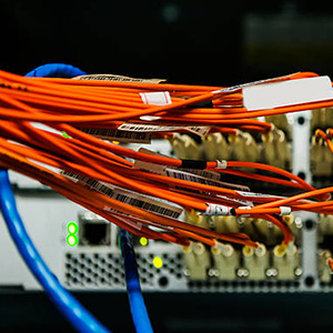
Each floor will have a telecommunication room, usually vertically aligned with the rooms on other floors. These rooms house network equipment, including routers, servers, and switches. Telecommunication rooms are connected by fiber optic cables running through vertical shafts, referred to as backbone or vertical cabling. Backbone fiber optic cables typically run at 10Gbps Ethernet speeds to provide sufficient bandwidth for the entire enterprise.
Work areas are individual workstations (e.g., PCs) arranged in cubicles. These work areas are connected to the telecommunication room on each floor using horizontal cabling. The copper or fiber optic cables in these horizontal runs generally support 1Gbps Ethernet speeds.
How to Pull Fiber Optic Cable Through Vertical Shafts:
Previously, backbone cabling was made of twisted pair copper cables, but today, it is usually multimode or single-mode fiber. Several tools are available to pull vertical backbone fiber cables, such as Gopher poles, cable casters, and pulling tapes. It is important to attach a pulling eye to protect the fiber cables and connectors during the pulling process.
How to Terminate a Vertical Backbone Fiber Optic Cable:
Backbone fiber optic cables typically come un-terminated, so you must terminate them using ST, SC, or LC connectors. While the termination process is not overly complex, it requires proper training to achieve good results.
Tools for Fiber Termination:
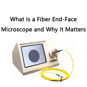
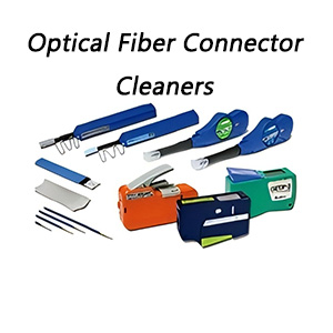
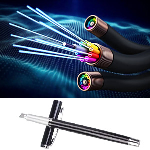
The necessary tools for fiber optic terminations include fiber optic cable strippers, Kevlar cutters, fiber cleavers, ST, SC, LC, or MTRJ fiber connectors, hand polishing pucks, fiber polishing films, and fiber inspection microscopes.
Fiber Cable Termination Steps:
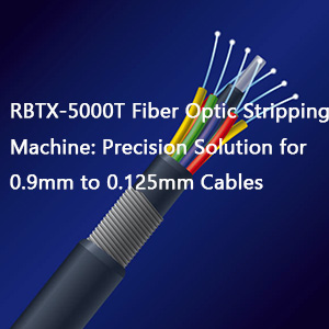
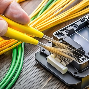
- Strip the Fiber: Fiber cables consist of a 3mm jacket, Kevlar strength member, and a 0.9mm buffer coating. To access the 0.125mm fiber cladding, you must remove the 3mm jacket with a fiber stripper, cut the Kevlar fibers with a Kevlar cutter, and strip the 0.9mm buffer down to the 0.125mm cladding using a fiber optic stripper.
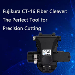
- Cleave the Fiber: After stripping the fiber to the 0.125mm cladding, insert the fiber into an SC, ST, or LC connector, then inject fiber optic epoxy into the connector using a syringe. Next, place the connector into a hot oven to cure the epoxy, which will secure the fiber. Once cured, use a fiber cleaver to trim the excess fiber at the connector tip.
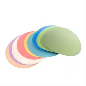
- Hand Polishing: The next step involves placing the connector (with the fiber secured inside) into a hand polishing puck to stabilize it during polishing. Then, polish the connector’s end face on a lapping film in a figure-8 motion for 10–15 cycles. Repeat this polishing process with progressively finer films, from 12μm to 3μm to 0.5μm.
- Inspection for Quality: The final step is inspecting the termination quality using a fiber optic inspection microscope. This device magnifies the connector end face by 200 to 400 times, allowing you to detect any scratches or imperfections. If the connector appears flawless, you can safely connect the fiber to the network.


