FREE SHIPPING On Orders Over US$200

Two fiber optic splitters can have the same number of ports yet serve different purposes. One may distribute light equally across several branches, while another sends a small share to a monitoring port. Some applications also need to preserve a defined polarization orientation. Choosing a fiber optic splitter therefore means matching its power distribution, wavelength and polarization characteristics to the components connected to it.
What Does a Fiber Optic Splitter Do?
A fiber optic splitter is a passive device that distributes input optical power among multiple output paths. It does not amplify the light or actively select which output receives it.
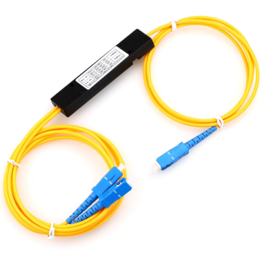
A 1×2 fiber optic splitter has one input and two outputs. A 1×4 device provides four output paths. The port configuration tells you how many connections are available, while the splitting ratio describes how power is shared.
For example, a 50:50 splitter divides power approximately equally between two outputs. A 90:10 splitter directs most of it to one branch and a smaller share to the other. Actual output power also reflects the device’s losses and manufacturing tolerances.
Match the Splitting Ratio to Each Branch
Start by identifying what the output branches need to do.
If two test paths require similar power, an equal split may be suitable. If one branch only monitors a signal, an unequal split may leave more power available for the main path.
For an equal-split device, increasing the number of outputs reduces the power available at each output for the same input. Check that every branch can still meet its requirements after allowing for the splitter, connectors and downstream fiber.
Use the specified insertion loss for each output when assessing this. Insertion loss includes both the effect of distributing power to other outputs and additional loss within the device. It should not be treated as an extra loss to add on top of the same splitting loss again.
The operating wavelength matters too. Confirm that the splitter’s specified wavelength range covers your source; its performance outside that range may differ.
Where PLC, FBT and PM Fit In
PLC and FBT describe different splitter technologies.
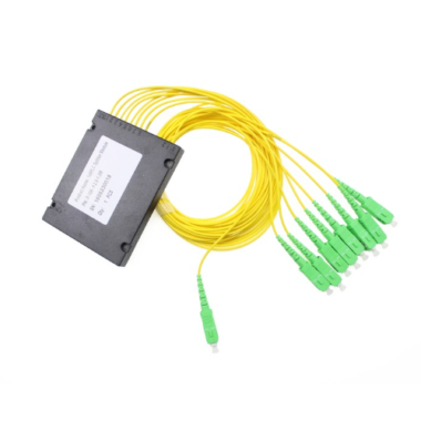
A PLC splitter, or planar lightwave circuit splitter, distributes light through an optical waveguide circuit. It is commonly used for multiple-output power distribution.
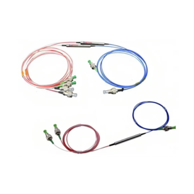
An FBT splitter, or fused biconical taper splitter, uses fused and tapered fibers to couple optical power between paths. Products are available with different splitting ratios and wavelength specifications.
PM, meaning polarization maintaining, describes an optical capability rather than a separate manufacturing technology. Both PM PLC splitters and PM fused-fiber splitters are available.
This distinction makes product selection clearer: choose the required port arrangement and power distribution, then determine whether the system also requires polarization maintenance.
When Do You Need PM Fiber Splitters?
Polarization describes the orientation of light’s electric field. In some systems, changes in that orientation affect how downstream components respond.
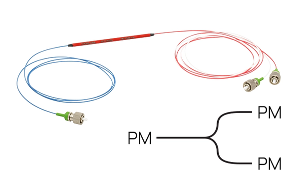
Consider a polarized light source feeding two measurement paths. If both paths require a particular input polarization, dividing the power is only part of the requirement. The splitter and its connections must also support that polarization requirement.
A polarization maintaining fiber splitter is designed for this type of application. When used with the specified input polarization and axis alignment, it distributes power while maintaining the intended polarization.
If your optical path has this requirement, compare the available PM Fiber Splitters against the source wavelength, output count and connection arrangement.
PM is not automatically necessary simply because a system uses single-mode fiber. The deciding factor is whether the application requires polarization to be maintained.
Also, a PM power splitter is different from a polarization beam splitter. A PM power splitter distributes power between branches; a polarization beam splitter separates orthogonal polarization components into different paths.
Specifications to Check for PM Fiber Splitters
Once a PM design is needed, review its optical specifications and connection requirements together.
| Specification | What to check |
|---|---|
| Wavelength range | It covers the source wavelength and expected variation. |
| Output count and splitting ratio | Each branch receives the intended share of optical power. |
| Insertion loss | The specified loss at each output fits the system’s power requirements. |
| Polarization extinction ratio | The stated polarization performance meets the application’s needs under comparable test conditions. |
| Working axis and connectors | Fiber-axis alignment, connector type and polish match the connected components. |
| Power handling and packaging | The device accepts the intended optical power and fits the installation’s space and operating conditions. |
Polarization extinction ratio, or PER, compares power in the intended polarization axis with power in the orthogonal axis. A higher value indicates stronger separation under the same measurement conditions.
Compare the conditions alongside the number. Wavelength, temperature, input alignment and whether connectors are included can affect how a PER specification should be interpreted.
For products marked slow-axis working, follow the specified slow-axis launch and connection requirements. Do not assume that every PM device uses the same alignment convention.
Confirm the Connections Before Ordering
A suitable splitter can still underperform if its connections do not match the optical design. Check the source polarization, PM fiber alignment and receiving components as one path. Matching connector shapes alone does not confirm correct polarization alignment.
For a PM PLC splitter, confirm the connector-key orientation with the supplier when it is not clearly documented. Also check pigtail lengths and package dimensions so the device can be installed without straining its fibers.
Choose the fiber optic splitter around what the outputs need: sufficient power, the correct wavelength range and, where required, maintained polarization. With these requirements defined, the product specifications become a practical selection guide.