FREE SHIPPING On Orders Over US$200
Every optical link has a power budget. As a signal travels through fiber, connectors, splices, splitters, filters and wavelength-division multiplexers, part of its optical power is lost. When the signal arriving at the receiver becomes too weak, the bit-error rate may increase or the link may stop operating.
A fiber optic amplifier compensates for part of this loss by increasing optical signal power without first converting the signal into an electrical data stream.
Optical amplifiers are used in applications such as:
- DWDM transmission systems
- Metropolitan and long-haul networks
- Data center interconnects
- CATV distribution
- Optical test systems
- Fiber sensing
- Specialized PON reach-extension systems
- Fiber lasers and scientific instruments
However, an amplifier cannot simply be inserted into any fiber link. Its wavelength, gain, output power, noise, saturation behavior and position must match the complete optical system.
What Is a Fiber Optic Amplifier?
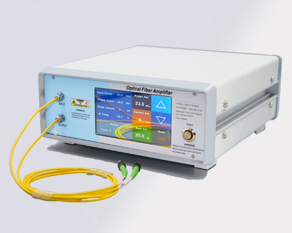
A fiber optic amplifier is an active optical device that increases the power of an optical signal while the information remains in the optical domain.
Depending on the technology, the gain medium may be:
- Rare-earth-doped optical fiber
- The transmission fiber itself
- A semiconductor gain chip
- A specialty doped fiber optimized for another wavelength or power range
An EDFA, for example, passes the signal through a section of fiber containing erbium ions. Pump-laser energy excites the ions, allowing stimulated emission to amplify compatible optical signals. Practical EDFA pump bands commonly include 980 nm and 1480 nm.
Optical Amplifier vs. Optical Repeater
An optical amplifier and an optical repeater are not equivalent.
| Function | Optical Amplifier | OEO Repeater or Regenerator |
|---|---|---|
| Signal conversion | Remains optical | Optical to electrical to optical |
| Optical power restoration | Yes | Yes |
| Pulse reshaping | No | Possible |
| Clock retiming | No | Possible |
| Noise removal | No | Partial or substantial regeneration |
| Wavelength transparency | Amplifier-band dependent | Transceiver dependent |
| Protocol awareness | Generally none | May depend on implementation |
| Main function | Increase optical power | Recover and retransmit data |
An optical amplifier can reduce the need for electrical regeneration, but it does not make light travel faster. It also does not correct timing errors, chromatic dispersion or waveform distortion.
How Does Optical Amplification Work?
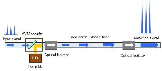
Although amplifier technologies use different physical mechanisms, they follow the same basic concept:
- Energy is supplied by a pump laser or electrical current.
- The gain medium is placed into an energized state.
- The incoming optical signal interacts with the gain medium.
- Additional photons are generated at compatible wavelengths.
- The output signal has greater optical power than the input.
The amplifier also introduces noise and has a finite energy capacity. As input power or total channel loading increases, gain may compress and the amplifier may approach saturation.
Main Types of Fiber Optic Amplifiers
1. Erbium-Doped Fiber Amplifier
The Erbium-Doped Fiber Amplifier, or EDFA, is the most established amplifier technology for optical communication around the 1550 nm region.
It uses erbium-doped fiber as the gain medium and is normally pumped at approximately 980 nm or 1480 nm. Its operating range commonly overlaps the C-band and, with a different design, the L-band.
Main Advantages
- High optical gain
- Suitable noise performance
- Simultaneous amplification of multiple DWDM channels
- Broad commercial availability
- Compatibility with common C-band and L-band transmission systems
- Availability in fixed-gain and variable-gain designs
Main Limitations
- Primarily limited to erbium gain bands
- Generates amplified spontaneous emission
- May require gain-flattening filters for multi-channel use
- Can enter saturation at high input or output power
- Does not correct dispersion or signal distortion
Common Applications
- DWDM line systems
- Booster amplification
- In-line span-loss compensation
- Receiver pre-amplification
- CATV distribution
- Optical test and measurement
- Fiber sensing
- Laboratory laser systems
2. Raman Fiber Amplifier
A Raman amplifier uses stimulated Raman scattering to transfer energy from one or more pump wavelengths to the signal.
In a distributed Raman system, part of the transmission fiber itself becomes the gain medium. This differs from an EDFA, where gain is concentrated inside a dedicated section of erbium-doped fiber.
Raman gain depends on the installed span, including fiber type, attenuation, connectors, splices and other loss-producing components.
Main Advantages
- Gain wavelength can be influenced by pump selection
- Distributed amplification can improve effective noise performance
- Can extend the usable reach of long optical spans
- Can complement EDFA gain
- Suitable for C-band, L-band and other engineered wavelength ranges
Main Limitations
- Requires high pump power
- Design depends strongly on the transmission span
- Needs additional optical-safety controls
- Pump interactions and nonlinear effects require careful engineering
- More complex to commission than a conventional EDFA
Hybrid Raman–EDFA Systems
Raman and EDFA technologies are frequently combined.
The Raman stage provides distributed gain along the transmission fiber, while the EDFA provides concentrated gain at a network node. Commercial optical systems use this combination to improve reach and noise performance.
3. Semiconductor Optical Amplifier
A Semiconductor Optical Amplifier, or SOA, uses an electrically driven semiconductor gain region.
Its construction is similar in concept to a semiconductor laser, but the device is designed to amplify an externally supplied optical signal rather than operate primarily as an independent laser source.
Main Advantages
- Compact size
- Electrical control
- Potential integration with photonic circuits
- Fast gain dynamics
- Availability outside the conventional EDFA wavelength range
- Suitability for switching, gating and test applications
Main Limitations
- Generally higher noise than low-noise EDFA designs
- Stronger gain saturation
- Polarization sensitivity in some designs
- Nonlinear distortion
- Limited output power for many communication applications
Commercial SOA-based systems are available for O-band and other applications where conventional C-band EDFAs are not suitable.
4. Erbium–Ytterbium-Doped Fiber Amplifier
An EYDFA uses fiber co-doped with erbium and ytterbium.
Erbium provides gain around the 1550 nm region, while ytterbium can improve pump absorption and support higher-power architectures. Erbium–ytterbium co-doped fibers are used in amplifier and laser systems over a broad range of output powers.
EYDFAs are commonly associated with:
- High-output CATV distribution
- Multi-port optical amplification
- High-split-count optical systems
- Laboratory sources
- Specialty high-power 1550 nm systems
“High power” should be expressed through an actual output-power specification, such as +23 dBm, +27 dBm or a watt-level value, rather than an undefined product category.
5. Specialty Rare-Earth-Doped Fiber Amplifiers
Other rare-earth elements can support amplification in different wavelength regions.
Examples include:
- Ytterbium-doped amplifiers near 1 μm
- Thulium-doped amplifiers near 2 μm
- Holmium-doped amplifiers in specialty infrared systems
- Neodymium-doped amplifiers for selected near-infrared wavelengths
These technologies are more common in laser processing, sensing, medical systems and scientific research than in conventional 1550 nm telecom links.
Amplifier Type vs. Amplifier Position
EDFA, Raman and SOA describe the amplification technology.
Booster, in-line and pre-amplifier describe the position or function in the network.
These two classification systems should not be mixed.
Booster Amplifier
A booster amplifier is installed after the optical transmitter or terminal equipment.
Its purpose is to increase launch power before the signal enters:
- A long fiber span
- A passive splitter network
- A high-loss multiplexer
- A CATV distribution system
Important specifications include:
- Saturated output power
- Total and per-channel output power
- Gain range
- Output-power stability
- Channel loading
- Nonlinear launch-power limit
In-Line Amplifier
An in-line amplifier is installed between two fiber spans.
It compensates for attenuation from the preceding span and provides sufficient power for the next span.
Important parameters include:
- Gain
- Output power
- Noise figure
- Gain flatness
- Gain tilt
- Channel transient control
- OSNR contribution
When several in-line amplifiers are cascaded, ASE accumulates and the OSNR gradually deteriorates.
Pre-Amplifier
A pre-amplifier is placed close to the receiver.
It increases the power of a weak incoming signal before detection.
A pre-amplifier generally prioritizes:
- Low noise figure
- High gain for weak inputs
- Stable operation
- Low polarization dependence
- Receiver compatibility
Commercial optical line systems often integrate separate booster and pre-amplifier sections with different gain ranges and control requirements.
Mid-Stage or Dual-Stage EDFA
A dual-stage EDFA contains two amplifier stages with an accessible point between them.
The mid-stage port may allow the system designer to insert:
- Gain-flattening filters
- Dispersion-compensation modules
- Optical add/drop components
- Monitoring devices
- Variable attenuators
- Application-specific filters
The EDFA itself does not necessarily add or remove wavelength channels. It provides an accessible location where another optical component can be inserted between amplification stages.
Key Fiber Optic Amplifier Specifications
Gain
Gain indicates how much the amplifier increases optical power.
Gain in dB = Output signal power in dBm − Input signal power in dBm
For example:
- Input signal: −20 dBm
- Output signal: +5 dBm
- Amplifier gain: 25 dB
The rated maximum gain may not be available across every wavelength, input-power level or channel-loading condition.
Saturated Output Power
Saturated output power describes the practical upper limit of useful output power.
As the amplifier approaches saturation:
- Gain decreases
- Channel interaction may increase
- Output no longer rises proportionally with input
- Gain flatness may change
An amplifier should therefore be selected by both gain and maximum output power.
Noise Figure
Noise figure describes how much the amplifier degrades the signal-to-noise ratio.
A lower value is generally preferable, especially for:
- Weak-signal pre-amplification
- Cascaded amplifier links
- Long-haul transmission
- Coherent optical systems
- Laboratory measurements
Gain, output power and noise figure are three of the primary parameters used to characterize optical amplifiers.
Amplified Spontaneous Emission
Amplified Spontaneous Emission, or ASE, is broadband optical noise generated inside the amplifier.
ASE can:
- Reduce OSNR
- Consume part of the amplifier’s output-power capacity
- Accumulate across several amplifier stages
- Affect receiver performance
- Create misleading total-power readings
EDFAs are a major ASE source in amplified optical networks, and their number, gain and position must be considered during system planning.
Operating Wavelength and Gain Bandwidth
Confirm whether the amplifier is designed for:
- C-band
- Extended C-band
- L-band
- C+L-band
- O-band
- A narrow specialty wavelength
- A broadband laboratory application
An EDFA designed for the C-band will not effectively amplify an 850 nm or conventional 1310 nm signal.
Gain Flatness
In a multi-channel system, gain may vary with wavelength.
Without gain flattening, one DWDM channel may leave the amplifier with substantially more power than another.
Gain-flattened EDFA designs are intended to maintain a more uniform gain level across a defined wavelength range.
Gain Tilt
Gain tilt describes the slope of the amplifier gain across the optical spectrum.
Even when total output power is correct, excessive tilt can produce poor channel-power uniformity.
Some optical line systems provide tilt-control functions, but their controllable range may depend on amplifier gain and operating mode.
Input-Power Range
The amplifier must operate correctly at the expected input level.
If input power is too low:
- ASE may become a large part of the output
- OSNR may be poor
- The useful signal may remain insufficient
If input power is too high:
- Gain compression may occur
- The amplifier may saturate
- Output-power limits may be exceeded
- Channel transients may increase
For WDM systems, determine whether the specification refers to:
- Total composite input power
- Input power per channel
Total Output vs. Per-Channel Output
A DWDM amplifier output of +23 dBm does not mean that every channel has +23 dBm.
For equal channel powers:
Per-channel power ≈ Total power − 10 log₁₀(number of channels)
For example, +23 dBm divided equally among 40 channels corresponds to approximately +7 dBm per channel before accounting for ripple and unequal loading.
Polarization-Dependent Gain
Polarization-Dependent Gain describes how gain changes with the signal’s state of polarization.
It is important in:
- Coherent transmission
- PM fiber systems
- Polarization-sensitive sensing
- Precision measurement
- Scientific optical systems
A PM EDFA must also preserve axis alignment throughout the input fiber, gain section, passive components and output fiber.
Control Modes
Depending on the design, an amplifier may support:
Automatic Gain Control
Maintains a target gain as input power changes.
Automatic Power Control
Maintains a target output-power level.
Automatic Current Control
Maintains a fixed pump-laser current.
Channel-Aware Control
Higher-level optical line systems may use channel monitoring and dynamic gain regulation to respond to channels being added or removed. Cisco optical amplifier modules, for example, combine gain regulation with per-channel optical monitoring.
Applications of Fiber Optic Amplifiers
DWDM and Long-Haul Networks

EDFA and Raman systems are widely used to compensate for span loss in wavelength-division-multiplexed optical networks.
One amplifier can support multiple wavelength channels, provided that:
- All channels fall within the gain band
- Total input and output powers remain within limits
- Gain flatness is sufficient
- OSNR remains acceptable
- Nonlinear launch-power limits are respected
Modern optical line systems combine booster, pre-amplifier, in-line EDFA and optional Raman amplification according to the span design.
Metro and Data Center Interconnect
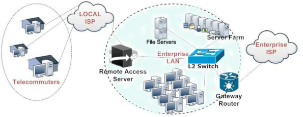
Amplifiers may form part of a managed optical line system connecting:
- Data centers
- Carrier hotels
- Metro aggregation sites
- Telecommunications offices
An amplifier should not be inserted into an ordinary client-optics link without checking:
- Transceiver wavelength
- Modulation format
- Launch power
- Receiver overload
- OSNR requirements
- Line-system compatibility
Some direct-detect client optics are not designed for arbitrary amplified operation.
CATV Distribution
CATV amplifiers commonly prioritize:
- High output power
- Low noise
- Stable power control
- Multiple output ports
- Low distortion
- Suitable return loss
High-power EDFA or EYDFA designs may distribute one optical source through several passive branches.
The required amplifier must be selected from the optical split ratio, path loss, receiver range and required performance of the analog or digital transport system.
Optical Test and Measurement
Laboratory EDFAs, SOAs and VOAs are used for:
- Receiver testing
- OSNR loading
- Transceiver characterization
- WDM system simulation
- Amplifier gain measurement
- Noise-figure measurement
- Optical-component qualification
Commercial laboratory EDFAs may provide low-noise and gain-flattened versions specifically for optical-system testing.
PON Reach Extension
Conventional PON systems are designed around defined passive-distribution-network loss budgets.
Optical amplifiers or regenerators may be introduced in specialized reach-extension designs, but this is not the normal configuration of every FTTH link.
ITU-T G.984.6 defines GPON reach extenders using optical-amplifier, OEO and hybrid architectures. ITU-T G.9807.2 provides corresponding concepts for extended-reach XG(S)-PON systems.
A reach extender must account for both downstream and burst-mode upstream transmission, wavelength plan, management and compatibility with the OLT and ONUs.
Fiber Sensing and Scientific Systems
Fiber amplifiers are also used in:
- Distributed sensing
- Interferometry
- Spectroscopy
- Coherent detection
- LiDAR
- Quantum-optics experiments
- Specialty laser systems
These applications may require narrow wavelength ranges, PM fiber, low relative intensity noise or customized control modes.
Limitations of Optical Amplification
An Amplifier Does Not Repair a Distorted Signal
It does not correct:
- Chromatic dispersion
- Polarization-mode dispersion
- Timing errors
- Pulse-shape distortion
- Incorrect extinction ratio
- Nonlinear penalties
- Data errors
An Amplifier Adds Noise
ASE reduces OSNR, particularly when several amplifiers are cascaded. A link may have sufficient optical power but still fail because signal quality is inadequate.
Higher Output Power Is Not Always Better
Excessive launch power can cause:
- Receiver overload
- Self-phase modulation
- Cross-phase modulation
- Four-wave mixing
- Stimulated Brillouin scattering
- Other fiber nonlinearities
Amplifiers Are Wavelength-Specific
A C-band EDFA is not a universal amplifier for every optical wavelength.
Amplifiers Require Power and Monitoring
Unlike passive components, amplifiers require:
- Electrical power
- Thermal management
- Pump-laser control
- Alarm monitoring
- Optical safety provisions
- Maintenance planning
How to Select a Fiber Optic Amplifier
| Selection Factor | Questions to Confirm |
|---|---|
| Application | DWDM, CATV, DCI, PON extension, sensing or laboratory use? |
| Amplifier technology | EDFA, Raman, SOA, EYDFA or another type? |
| Position | Booster, in-line, pre-amplifier or dual-stage? |
| Wavelength | C-band, L-band, O-band or a specialty wavelength? |
| Input power | Total input and per-channel input? |
| Gain | How much span or component loss must be compensated? |
| Output power | Total and per-channel requirement? |
| Noise figure | What OSNR margin is available? |
| Channel count | Single-channel or multi-channel? |
| Gain flatness | How uniform must the channels be? |
| Control mode | AGC, APC, ACC or network-managed operation? |
| Polarization | Standard single-mode or PM amplification? |
| Connectors | LC/UPC, LC/APC, SC/APC or bare fiber? |
| Monitoring | Input/output power, pump current, temperature and alarms? |
| Management | Local display, Ethernet, SNMP, RS-232 or another interface? |
| Form factor | Module, benchtop, 1U rack or integrated line-system card? |
Basic Selection Example
Assume a single-channel C-band link has:
- Transmitter output: 0 dBm
- Fiber loss: 18 dB
- Connector and component loss: 4 dB
- Receiver sensitivity: −20 dBm
- Desired engineering margin: 3 dB
Received power without amplification:
0 − 18 − 4 = −22 dBm
To maintain a 3 dB margin above sensitivity, the target receiver level is:
−20 + 3 = −17 dBm
The approximate required net gain is:
−17 − (−22) = 5 dB
However, amplifier selection cannot stop at 5 dB. It must also verify:
- Noise figure
- Receiver overload
- Minimum and maximum input power
- Output saturation
- ASE
- Future loss variation
- Nonlinear limits
- Connector and splice tolerances
In many practical cases, changing the transceiver class or correcting excessive passive loss may be more appropriate than adding an amplifier.
Common Selection Mistakes
Selecting Only by Maximum Gain
The amplifier may have sufficient gain but insufficient output power or poor noise performance.
Confusing Total Power With Per-Channel Power
This is particularly dangerous in DWDM and CATV systems.
Using an EDFA at 1310 nm
A conventional C-band or L-band EDFA will not provide useful gain for a standard 1310 nm O-band signal.
Ignoring Receiver Overload
An amplifier can produce too much power as easily as too little.
Cascading Amplifiers Without OSNR Analysis
Each stage adds ASE.
Describing SDH, DWDM and CATV as Different Amplifier Technologies
They are applications or product optimizations, not fundamental gain mechanisms.
Assuming Every FTTH Link Needs an Amplifier
Most standard PON deployments rely on the specified passive link budget. Amplification is reserved for engineered extension cases.
Treating an Amplifier as a Replacement for Maintenance
An amplifier should not be used to conceal:
- Dirty connectors
- Damaged fiber
- Poor splices
- Incorrect splitter ratios
- Excessive macrobending
- Faulty transmitters
Frequently Asked Questions
Does a fiber optic amplifier increase data speed?
No.
It increases optical power. The data rate remains determined by the transmitter, receiver and communication standard.
Can one EDFA amplify multiple DWDM channels?
Yes, when the channels fall within its gain band and the total channel loading remains within its specifications.
Can an EDFA amplify 1310 nm?
A conventional C-band or L-band EDFA cannot. An O-band SOA, Raman system or another specialty amplifier may be required.
What is the difference between gain and output power?
Gain is the increase relative to input power.
Output power is the absolute power leaving the amplifier.
What is the difference between a booster and a pre-amplifier?
A booster is placed after the transmitter and prioritizes high launch power.
A pre-amplifier is placed before the receiver and normally prioritizes low noise.
Why does an optical amplifier reduce OSNR?
A real amplifier generates ASE noise in addition to amplifying the signal. As amplifier stages accumulate, the ratio between signal power and optical noise generally deteriorates.
Can an amplifier replace a repeater?
It can extend the distance between regenerators, but it cannot reshape or retime the signal.
Is Raman amplification better than EDFA?
Neither is universally better.
EDFA is mature and relatively straightforward to deploy. Raman amplification can improve effective span performance but requires more complex engineering and safety controls.
Is a PM EDFA always necessary for coherent transmission?
Not necessarily.
Many coherent telecom systems use ordinary single-mode line amplifiers and polarization-diverse receivers. PM EDFAs are used when the application specifically requires preservation of a defined polarization axis.
Conclusion
Fiber optic amplifiers are essential in many optical transmission, distribution and measurement systems, but they are not universal signal-repair devices.
EDFA technology provides mature C-band and L-band amplification for DWDM, CATV and optical test systems. Raman amplification creates gain within the transmission fiber and can improve long-span performance. SOAs provide compact semiconductor-based amplification, while EYDFAs and other rare-earth-doped amplifiers address higher-power or specialty wavelength applications.
Correct selection requires consideration of:
- Amplifier technology
- Network position
- Operating wavelength
- Input-power range
- Gain
- Saturated output power
- Noise figure
- ASE and OSNR
- Channel count
- Gain flatness
- Polarization
- Monitoring and control
Fiber-Life supplies configurable optical amplifier solutions for telecommunications, CATV, DWDM, sensing and laboratory applications. Available configurations may include C-band and L-band EDFAs, booster amplifiers, in-line amplifiers, pre-amplifiers, high-power designs and polarization-maintaining options. Final specifications should be established from the complete optical link budget and system requirements rather than gain alone.