FREE SHIPPING On Orders Over US$200
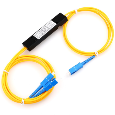
Fiber optic splitters are passive optical components that divide an incoming optical signal into two or more output signals. They are widely used in passive optical networks, fiber-to-the-home deployments, telecommunications systems, optical monitoring, CATV networks, laboratories, and fiber sensing applications.
Two of the most common splitter technologies are Planar Lightwave Circuit (PLC) and Fused Biconical Taper (FBT). Although both devices perform the same basic function, they differ significantly in manufacturing technology, wavelength performance, splitting configuration, scalability, packaging, and cost.
Choosing between them should not be based on price alone. The correct choice depends on the required port count, splitting ratio, operating wavelength, environmental conditions, available installation space, and optical performance requirements.
What Is a PLC Splitter?
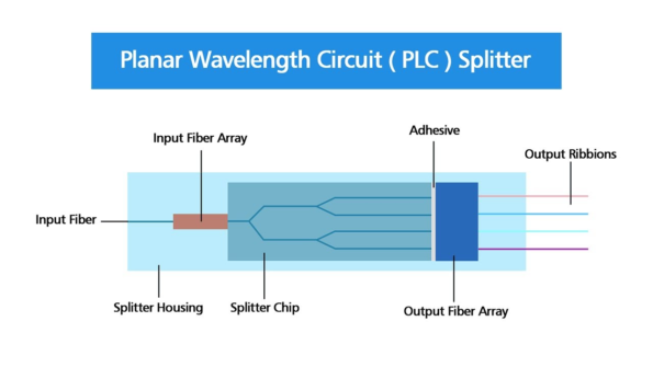
A PLC splitter is manufactured using a planar silica waveguide circuit. Optical waveguides are formed on a substrate using precision deposition and photolithographic processes, allowing the incoming optical power to be distributed across multiple output channels.
PLC technology is particularly suitable for high-port-count and equal-ratio splitting configurations. Common configurations include:
- 1×2
- 1×4
- 1×8
- 1×16
- 1×32
- 1×64
- 2×N configurations
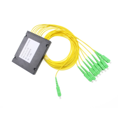
Commercial PLC splitters commonly support a broad operating wavelength range of approximately 1260 to 1650 nm, making them suitable for PON, FTTH, FTTB, and other broadband optical distribution systems. PLC devices are also available in bare-fiber, blockless, ABS box, tray-mount, rack-mount, LGX cassette, and plug-in packages.
What Is an FBT Splitter?
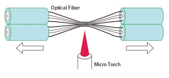
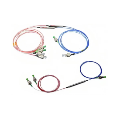
An FBT splitter is manufactured by placing two or more optical fibers together, heating them, and stretching the fused section to form a tapered coupling region. During production, the coupling ratio is monitored until the required amount of optical power is transferred between the fibers.
FBT technology is commonly used for low-port-count configurations such as 1×2 and 2×2. Higher-output configurations can also be produced by cascading multiple coupling stages.
One of the main advantages of FBT technology is its flexibility in splitting ratio. In addition to equal 50/50 splitting, FBT splitters can be manufactured with asymmetric ratios such as:
- 90/10
- 80/20
- 70/30
- 60/40
- 95/5
- 99/1
This makes FBT splitters useful for optical power monitoring, signal tapping, fiber sensors, laboratory systems, and applications where the outputs do not require equal optical power.
FBT products are not limited to only three exact wavelengths. Depending on the fiber and taper design, they may be optimized for single-window, dual-window, triple-window, wideband, or custom-wavelength operation.
PLC Splitter vs. FBT Splitter: Quick Comparison
| Parameter | PLC Splitter | FBT Splitter |
|---|---|---|
| Manufacturing technology | Planar silica waveguide circuit | Fused and tapered optical fibers |
| Typical port configurations | 1×2 to 1×64 and 2×N | Commonly 1×2, 2×2 and low-port-count cascades |
| Splitting ratio | Commonly equal splitting; asymmetric versions may also be available | Equal or asymmetric ratios |
| Operating wavelength | Typically broadband, such as 1260–1650 nm | Product-dependent single, dual, triple or wide wavelength windows |
| Channel uniformity | Generally better for equal, high-port-count splitting | Good at low port counts; depends more strongly on wavelength and cascade design |
| Scalability | Well suited for large splitting configurations | Less efficient for large port counts when multiple stages are cascaded |
| Package size | Compact relative to the number of output ports | Compact at low port counts but larger when multiple stages are cascaded |
| Typical cost advantage | Better cost per output at higher port counts | Often more economical for simple, low-port-count applications |
| Typical applications | PON, FTTH, FTTB, high-density optical distribution | Monitoring, tapping, sensing, CATV, laboratories and asymmetric splitting |
1. Operating Wavelength
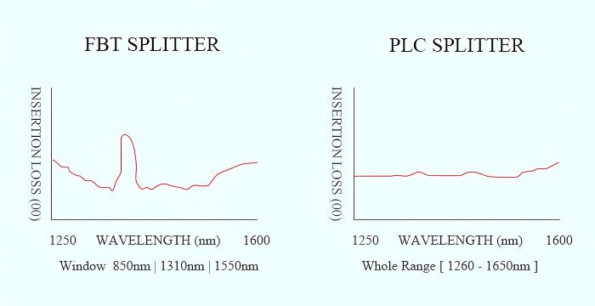
PLC splitters are designed for broadband operation. Many standard single-mode PLC products cover the full 1260–1650 nm range, allowing the same splitter to carry multiple PON and telecommunications wavelength bands.
It is more accurate to describe this as a broad operating wavelength range, rather than saying that the wavelength is “adjustable.” The splitter does not actively tune its wavelength; it is designed to maintain specified optical performance across a defined range.
FBT splitters are typically optimized around one or more specified wavelength windows. Standard products may support 1310 nm, 1490 nm, 1550 nm, dual-window 1310/1550 nm operation, or wider wavelength ranges. Other wavelengths can also be produced by selecting an appropriate fiber and taper design.
Therefore, the wavelength specification of an FBT splitter should always be checked on the individual product datasheet rather than inferred solely from the FBT manufacturing technology.
2. Splitting Ratio and Port Configuration
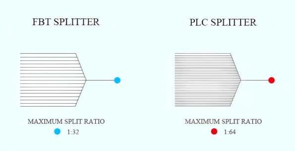
PLC splitters are most commonly used for equal optical power distribution. For example, a 1×8 PLC splitter is designed to divide the input signal among eight output channels with closely controlled insertion-loss uniformity.
Standardized 1×N and 2×N configurations make PLC splitters convenient for scalable network planning. A single compact PLC device can provide 16, 32, or 64 outputs without requiring a large cascade of individual 1×2 couplers.
FBT technology provides greater flexibility when an unequal split is required. A 90/10 FBT splitter, for example, can direct most of the optical power through the main transmission path while sending a smaller portion to monitoring equipment.
For this reason, FBT splitters are often preferred for signal tapping and power-monitoring applications, while PLC splitters are generally preferred for large-scale equal distribution.
3. Insertion Loss and Channel Uniformity
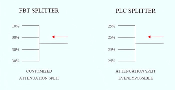
Any passive splitter introduces optical loss. The theoretical splitting loss increases as the number of output ports increases, while the actual device also adds excess loss from the manufacturing process, fibers, splices, and connectors.
PLC technology generally provides better channel-to-channel uniformity in high-port-count equal-splitting applications. Its planar waveguide structure allows the output channels to be formed within a controlled integrated circuit.
An FBT splitter can provide excellent performance in a 1×2, 2×2, or other low-port-count configuration. However, when many FBT stages are cascaded to obtain a larger number of outputs, insertion-loss variation and accumulated excess loss become more difficult to control.
This does not mean that every FBT splitter has poor uniformity. Performance depends on the port count, splitting ratio, wavelength range, taper design, manufacturing quality, and number of cascaded stages.
4. Size and Installation Density
PLC splitters offer a major packaging advantage when many output ports are required. A planar splitter chip can distribute the signal to multiple outputs within a relatively compact package, making PLC splitters suitable for:
- Optical distribution frames
- Fiber termination boxes
- Optical network terminals
- High-density patch panels
- Rack-mount and LGX systems
- Outdoor FTTH distribution enclosures
PLC technology is widely used in high-density FTTH applications specifically because 1×N and 2×N configurations can be integrated into compact packages.
A basic 1×2 FBT splitter can also be very compact. The size disadvantage mainly appears when multiple FBT couplers must be cascaded to produce a high-port-count splitter. In that situation, the completed assembly requires more fiber routing, more coupling stages, and a larger protective enclosure.
5. Temperature Stability and Reliability
Environmental performance should be compared using the actual product specifications rather than applying one fixed temperature range to every PLC or FBT splitter.
Many PLC splitters are specified for operation from approximately −40°C to +85°C. However, qualified FBT splitters are also available with operating temperature ranges such as −40°C to +70°C or −40°C to +85°C. The exact rating depends on the component design, fiber coating, adhesive, package, and qualification standard.
For outdoor cabinets, industrial installations, or environments with significant temperature variation, buyers should compare at least the following parameters:
- Operating temperature
- Storage temperature
- Temperature-dependent loss
- Wavelength-dependent loss
- Return loss
- Directivity
- Polarization-dependent loss
- Connector performance
- Applicable Telcordia or IEC qualification requirements
Reliability should not be evaluated only by stating that one technology has a higher “failure rate.” A more meaningful comparison considers the number of cascaded stages, splice points, packaging method, material quality, environmental testing, and manufacturer process control.
6. Cost
FBT splitters are often more economical for simple configurations such as 1×2 or 2×2, particularly when a specific asymmetric coupling ratio is required.
PLC splitter manufacturing involves a precision waveguide chip and more complex fabrication processes. However, as the output count increases, PLC technology can provide a lower cost per output because a single planar device replaces a cascade of multiple fused couplers.
The cost comparison can therefore be summarized as follows:
- For low-port-count or asymmetric splitting, FBT is often more cost-effective.
- For high-port-count equal splitting, PLC generally provides better scalability and overall system value.
- Connectors, fiber length, package type, testing grade, and customization may affect the final price as much as the splitter technology itself.
How to Choose Between a PLC and FBT Splitter
Choose a PLC splitter when:
- The system requires 1×8, 1×16, 1×32, 1×64, or another high-port-count configuration.
- Optical power must be distributed evenly across all output channels.
- The application requires broadband operation across multiple telecommunications wavelengths.
- Installation space and port density are important.
- The splitter will be deployed in a PON, FTTH, FTTB, or centralized optical distribution network.
- Low channel-to-channel loss variation is required.
Choose an FBT splitter when:
- The application requires a 1×2, 2×2, or another relatively low-port-count configuration.
- An asymmetric split such as 90/10, 80/20, or 70/30 is required.
- The device will be used for optical monitoring, signal tapping, sensing, testing, or laboratory integration.
- The operating wavelength is clearly defined and matches the splitter specification.
- Initial component cost is an important consideration.
- A custom coupling ratio is more important than high-output scalability.
Is a PLC Splitter Always Better Than an FBT Splitter?
No. PLC splitters generally provide better scalability, broadband performance, and channel uniformity for high-port-count equal distribution. However, these advantages do not make PLC the best choice for every system.
For example, using a 1×8 equal-ratio PLC splitter for an application that only requires a 90/10 monitoring tap would add unnecessary outputs and optical loss. In that case, a purpose-built 1×2 FBT splitter would be a more appropriate solution.
The best splitter is the one whose optical specifications and configuration match the actual network design.
Conclusion
PLC and FBT splitters perform the same fundamental task, but they are optimized for different requirements.
A PLC splitter is usually the preferred choice for broadband, equal-ratio, high-port-count optical distribution, particularly in PON and FTTH networks. It offers compact packaging, good channel uniformity, and efficient scalability.
An FBT splitter remains an effective and economical solution for low-port-count systems, custom or asymmetric splitting ratios, optical monitoring, laboratory testing, sensing, and wavelength-specific applications.
Before selecting a splitter, evaluate the required port configuration, coupling ratio, operating wavelength, insertion loss, uniformity, environmental rating, package type, connector interface, and available optical power budget. Comparing these parameters will produce a more reliable result than choosing solely by splitter technology or unit price.