Definition Of Optical Circulator:
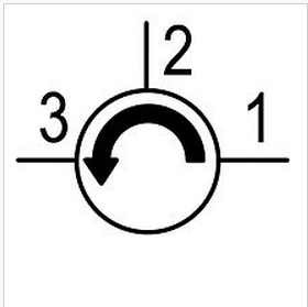
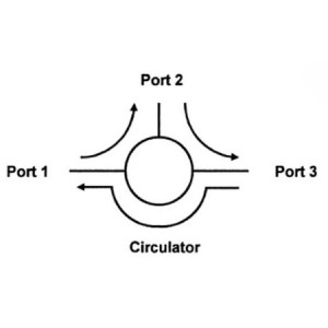
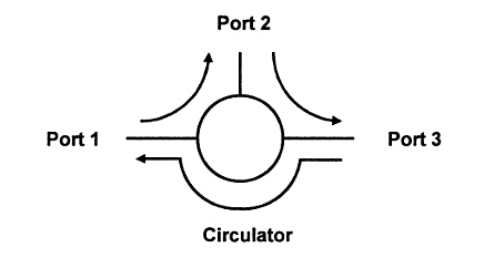
A Optical circulator is a multi-port non-reciprocal device that sequentially directs incident waves from any of its ports to the next port, as determined by a static magnetic field. For instance, if a signal is input through Port 1, it can only be output from Port 2; similarly, a signal input through Port 2 can only be output from Port 3, and so on, hence the name “optical circulator.”
Features and Applications Of Optical Circulator:
Optical circulators, also known as isolators, are distinguished by their ability to transmit high-frequency signals in one direction. They control the propagation of electromagnetic waves along a specific circular path. This characteristic is particularly useful between the output of high-frequency power amplifiers and the load, serving an independent and mutually “isolating” function. Even when the load impedance varies, or in cases of open or short circuits, it does not affect the operating state of the power amplifier, thus protecting it.
Principle Of Optical Circulator:
The unidirectional transmission principle of optical circulator is due to the use of ferrite gyromagnetic materials. Under the combined action of an external high-frequency wave field and a constant direct current magnetic field, these materials exhibit gyromagnetic properties, also known as tensor permeability characteristics. It is this gyromagnetic characteristic that causes electromagnetic waves propagating in the ferrite to undergo polarization rotation (Faraday effect) and strong absorption of electromagnetic wave energy (ferromagnetic resonance). Utilizing this gyromagnetic phenomenon, compact, wideband, and low-insertion-loss isolators and circulators are manufactured, widely used in various fields.
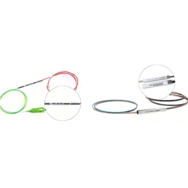
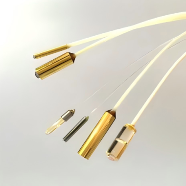
Structure Of Optical Circulator:
Optical circulators use a junction stripline structure, with a dual Y-shaped central conductor placed between two ferrite samples to form a sample junction. Three magnets are placed around the sample junction to generate a uniform and constant magnetic field. By converting the stripline to a coaxial line and through precise design, good matching between the circulator and the coaxial line is achieved, meeting the performance requirements of isolators and circulators. In the case of load mismatch, reflected energy will flow to the external absorption resistor along the designated direction and be absorbed by the resistor.
Port Components Of Optical Circulator:
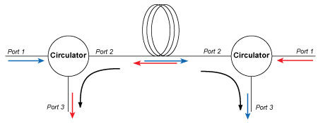
As a three-port device, when Port 1 is the input and Port 2 is the output, Port 3 acts as the isolation port, through which energy hardly penetrates. In UHF readers, optical circulators usually transmit signals in a clockwise direction. When Port 1 is used as the TX output, the RF signal will flow through Port 2, and Port 3 is the RX isolation port. The specific isolation degree should refer to the device parameters and layout effects. Conversely, when Port 2 receives signals as a transceiver multiplexing end, the signal will enter Port 3 in a clockwise direction. At this time, the energy leaking to the TX port is very small and can be neglected. However, the energy leaking from TX to the RX port greatly affects the sensitivity of the receiver and the actual recognition effect. Therefore, it is necessary to add an attenuator at the RX end according to the parameters of the receiving end LNA to effectively isolate the TX leakage signal. But this also brings a problem: the useful signal received by the RX end is already very small, and in the process of attenuating the TX leakage signal, the useful signal at the RX end is further weakened, affecting the reception of the LNA. Therefore, using a circulator for transceiver isolation can only be effective to a certain extent. For a given TX output power and ERP that does not exceed the relevant regulations, to improve the receiver sensitivity, it is necessary to consider increasing the isolation between the transmission and reception paths, and there are many methods to do this, depending on the specific needs.