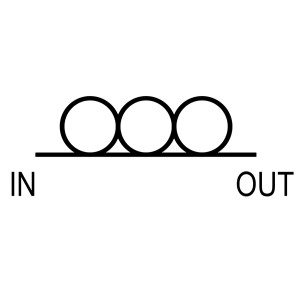
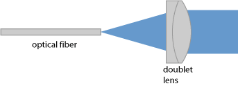
A device that fiber collimates the light coming out of an optical fiber, or emits collimated light into an optical fiber. In many cases, it is necessary to convert the output light from an optical fiber into a collimated beam in free space. In theory, a collimating lens (as shown in Figure 1) can meet this requirement. However, the lens requires that the distance between the optical fiber port and it is fixed, approximately equal to its focal length. In practice, it is more convenient to use a fiber collimator. There are two different types of fiber collimators:
One type of collimator is designed to be in direct contact with the bare fiber. This is the cheapest and simplest method, but this type of collimator is usually permanently attached to the fiber.
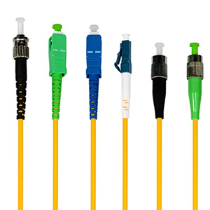
Another type of fiber collimator is a mechanical cross section between the optical connector, for example, FC or SMA type; it is not usually used for bare fiber. This type of collimator can be easily installed or removed from the fiber with the connector.
The same device can also be used to launch a collimated beam into a fiber, or for fiber-to-fiber coupling: first use a first collimator to collimate the light emitted from the first fiber, and then use another collimator to focus the collimated beam into the second fiber. In general, fiber connectors can be seen as a natural cross section between fiber optics and free space optics.
Another application is to combine the back reflector with additional optical elements. For example, a Faraday rotator can be inserted to obtain a fiber Faraday reflector, or a quarter wave plate can be inserted to obtain a half wave plate reflector. In some other cases, fiber filters or saturated absorbers can be used.
Collimated beam size
The beam radius of the collimated beam obtained in different situations is different. Sometimes, the beam diameter is comparable to the fiber diameter, for example, 125μm; in this case, the Rayleigh length is less than 1 cm. In some cases, the beam diameter needs to be several millimeters or even larger.
Single-mode fiber is a relatively simple case. In this case, the beam radius can be accurately calculated using the following formula:
It is assumed that the fiber mode beam shape is approximately Gaussian, so that the formula for the half angle of the beam divergence θfiber can be used.It is also assumed that the distance between the fiber port and the lens is approximately equal to the focal length f. If the distance is too small, the beam will diverge, while if the distance is too large, the beam will converge to a focal point at a certain distance. It is usually better to have a slightly larger distance, where the beam focus can be obtained within the working distance. The longer the focal length, the less important the front-to-back position.The smaller the fiber mode size, the larger the resulting beam divergence angle, and therefore the larger the collimated beam for a given focal length. That is, the shorter the wavelength, the smaller the resulting mode size and the larger the output beam. When the wavelength is short enough, this effect is more obvious after the fiber enters the multimode region. For the above reasons, the visible guide beam of the infrared beam does not give the exact size of the infrared beam. In addition, the exact fiber position required for collimation is wavelength-dependent, especially when an achromatic prism is not used.The divergence angle of the output beam of a multimode fiber (i.e., the collimated beam size) is related to the light exit conditions, especially the fiber (e.g., bending). Generally speaking, its beam divergence angle is larger than that of single-mode fiber. Fiber collimators can be used in situations with different collimated beam sizes, that is, corresponding to situations with different focal lengths. The larger the collimated beam size, the longer the device needs to be and the larger the diameter. Some fiber collimators have adjustment screws to control the beam direction (combined with angle adjustment) or to fine-tune the front and back position (adjust the focus or working distance). For collimators without adjustment screws, additional optomechanical devices are required to position the collimator.
Type of lens used
Collimators can use different types of lenses. Standard telecom fibers and other types of optical fibers often use graded index lenses (GRIN lenses) because they are relatively cheap and small. However, they are not suitable for larger beam diameters, for example, larger than a few millimeters. In such cases, ordinary single lenses or double lenses can be used, which are usually spherical, but sometimes non-spherical. This is required when the collimated beam needs to propagate over long distances, such as when long Rayleigh lengths are required in free-space optical communications. Special cases require special lenses. For example, when the beam contains light of different wavelengths, an achromatic doublet is required, otherwise it is not possible to collimate all wavelengths. When the light coming out of the fiber has a large beam divergence, an aspherical lens can be used to reduce beam distortion.
Insertion loss
The insertion loss of a single fiber collimator is usually very small, in the order of 0.2 dB or less. It depends on many factors, such as anti-reflection coatings and dirt on the lenses. However, these factors have no effect when using bare fibers or connectorized fibers.The insertion loss of a pair of couplers used for coupling between fibers can be greater than the sum of the insertion losses of the two devices. Especially in the case of single-mode fibers, it is very important to achieve good mode matching. Of course, the collimators should have collimated beams of the same size. Depending on the specific front and back position of the fibers in the collimator, the ideal situation is that the distance between the collimators is not zero. In this case, other optical elements can also be inserted, such as optical filters or polarizers.
The purpose of tilted fiber ports
Tilted fiber ports are often used to suppress light that is back-reflected from the fiber end face into the fiber core, that is, to maximize return loss. However, a tilted port will also reflect the output beam. Some fiber connectors have tilted fiber interfaces, which can be compensated for with a tilted fiber clamp. Otherwise, the beam emerging from the fiber will be directed at a certain angle to the lens. After passing through the lens, the beam direction is in the same direction as the fiber (assuming accurate front-to-back and lateral positioning), but will be offset from the center of the lens. This will also increase insertion loss and reduce beam quality if reflections, scattering, etc. occur at the edges.