A seamless connection between MPO and LC optical transceiver modules can be established using fiber patch cables, providing a versatile solution for modern networking infrastructure.
In the current era of network technology, the question arises: how are optical transceiver modules within data centers interconnected? The market abounds with MPO and LC interface modules, which are frequently utilized. When faced with the challenge of connecting modules that possess distinct interfaces, UnitekFiber offers a concise guide to facilitate this process.
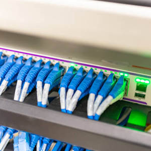
MPO and LC fiber patch cables are the key to establishing a link between these modules. For interfacing modules with unique ports, we employ MPO backbone fiber patch cords, LC duplex fiber patch cords, fiber optic adapter panels, MPO-LC fiber distribution boxes, and an array of fiber optic cabling solutions.
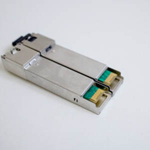
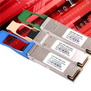
Our discussion typically revolves around the connections of high-density QSFP+ optical transceiver modules and the more common SFP+ modules, as well as the integration of CFP optical transceivers with SFP+ modules.
Direct Connection Solution
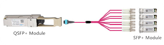
When it comes to connecting an 8-core QSFP+ optical transceiver module featuring an MPO interface to four dual LC interface optical modules, an MPO-LC breakout fiber jumper is employed. However, this straightforward connection scheme is confined to use within the same rack.
Interconnect Options
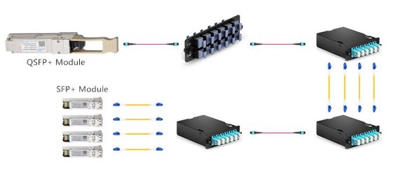
The visual representation illustrates the interconnection method between a QSFP+ optical module and an SFP optical module. The QSFP+ and SFP+ modules on either side are connected to the MPO backbone fiber jumper and the LC duplex fiber jumper, respectively. A fiber adapter panel is essential between these two jumpers, with the MPO backbone jumper and the MPO-LC fiber being wired and connected accordingly. This secondary connection technique allows for equipment interchangeability at both ends of the fiber link, as depicted in the subsequent diagram.
Another visual showcases a distinct interconnection method between QSFP+ and SFP+ optical modules. This scheme diverges from the previous by introducing optical fiber access equipment at the termination point of the SFP+ optical module. It is then connected to the SFP+ optical module via a fiber optic adapter panel and an LC dual-core breakout fiber jumper. However, this method requires that the SFP+ optical module ports be housed within the same chassis. The limitation here is the reduced flexibility at the SFP+ optical module end, meaning that this connection scheme does not permit the interchange of optical fiber access equipment there.
Cross-connect Solution
Two approaches can facilitate the cross-connection from a QSFP+ optical module to an SFP+ optical module. The primary difference lies in the aspect of the QSFP+ optical module. The first cross-connection scheme generally involves the use of MPO backbone fiber jumpers, MPO-LC fiber distribution boxes, and LC duplex fiber jumpers. The second cross-connect solution is more intricate, requiring not only the fiber optic equipment used in the first solution but also a fiber optic adapter panel. This method is particularly well-suited for applications with extended distribution ranges. It is crucial at this juncture to ensure that the backbone optical cable within the splice tray remains intact.