Summary:
This article focuses on single-fiber (not MT) PC ferrules. While the advice is applicable to APC polishing, those connectors require additional considerations.
Content:
Customers often seek guidance on developing a fiber optic polishing process. Although there are many details to consider, the process can be summarized in five basic steps.
Step 1: Define Your Objectives
When crafting a polishing process, clarify your acceptance criteria and targeted yields, and ensure you can accurately measure and quantify pass/fail results. For instance, do your polished ferrules need to meet end-face geometry specifications such as those in Telcordia GR-326? Virtually all polished fiber optic ferrule end-faces must meet some visual appearance specifications. What criteria will you use to determine acceptable results?
I highly recommend initially aiming to meet GR-326 geometry requirements and IEC 61300-3-35 visual requirements, with a minimum yield expectation of 95% passing.
Step 2: Ensure Proper Equipment
Ideally, start with brand-new polishing equipment. The precision of the equipment dimensions is crucial for process capabilities. Well-maintained polishing machines can last for decades, so follow the manufacturer’s maintenance recommendations.
Polishing fixtures wear out more quickly, depending on usage. If you cannot achieve acceptable results, especially in Apex Offset, you may need new fixtures.
Highly recommend measuring geometries during process development using an interferometer, an invaluable, albeit expensive, tool. If the cost is prohibitive, consider renting or borrowing one.
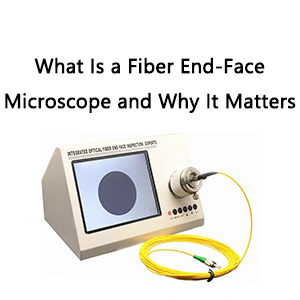
Ensure your equipment can properly measure what you need, especially for visual inspection. For example, if you need to meet single-mode requirements of IEC 61300-3-35, does your microscope have a high-resolution system as defined within the spec? If inspecting APC ferrules, ensure you have the correct adapter.
Step 3: Conduct a Trial Run
Fiber Optic Center offers Recommended Polishing Procedures for popular platforms like Domaille and Seikoh Giken. However, due to variations in ferrule material, connector design, and machine/fixturing dimensions, you may need to modify some settings. Use these recommendations as a starting point and adjust as needed based on your results.
Step 4: Adjust Your Process, Focusing on Radius
Achieving consistent Radius values is critical. Radius is the first geometry parameter to control because it indicates consistency in polishing pressure and the amount of ferrule material removed, impacting all results, including visual appearance and angle.
After polishing, use an interferometer to measure geometry, focusing on Radius values. Aim for a stable Radius variation of less than 2mm on one plate of ferrules. If the variation is higher, you may have a process issue or need new fixtures.
To decrease or increase Radius values, adjust pressure or use rubber pads of different hardness.
Step 5: Conduct a Visual Inspection
Customers will require visual inspection. After achieving desired geometry values, inspect the end-face for defects like pits and scratches. Pits can often be resolved by increasing time during intermediate polishing steps. Fine scratches may indicate insufficient time or pressure in the final polishing step.
Evaluate other major visual defects like shattered fibers, core cracks, or no visible fiber. These defects often stem from issues other than polishing, such as cleaving, handling, or curing temperatures. Address these root causes to prevent them from happening.
Final Thoughts:
Cleaning is critical, as polishing removes material, similar to sanding wood. Thoroughly clean the fixture and ferrules between each polishing step to prevent contamination.
Focus on preventive action, not just corrective action. Implement a statistical process control system to track and analyze data, preventing problems before they occur. This proactive approach will help maintain high yields.