FREE SHIPPING On Orders Over US$200

A fiber optic trunk cable can have the right length and still be unsuitable for a connection. Its connectors may not match the installed panels, its fiber arrangement may differ from the equipment requirements, or its polarity may not fit the complete link. These details are easier to resolve before ordering. For data center and building networks, a practical starting point is to map the connection, confirm the optical requirements and measure the actual cable route.
Where a Fiber Optic Trunk Fits in the Network
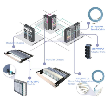
A fiber optic trunk groups multiple fibers into a shared cable route between distribution points, racks or equipment areas. It forms part of the network’s cabling backbone, carrying fibers that can serve several connections.
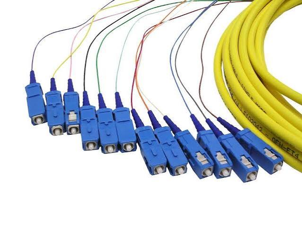
This article focuses on pre-terminated fiber trunk cables: assemblies supplied with connectors already fitted. They reduce the amount of termination work needed onsite, although inspection and installation testing are still necessary.
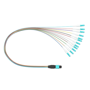
MPO and MTP® connectors are common on high-density trunks. Other configurations use individual connectors, such as LC, at the cable ends. MTP® is US Conec’s brand of MPO connectors, rather than a separate type of optical fiber.
The term “trunk” describes the cable’s role in the network. It does not, by itself, specify its connectors, supported distance or data rate.
Map the Connection Before Choosing the Cable
Start by identifying what connects to each end of the trunk. The answer may be a cassette, an adapter panel or a compatible optical transceiver.
A cassette is a module that organizes fiber connections, often presenting an MPO interface at the rear and LC ports at the front. In this arrangement, the trunk connects the cassettes, while LC patch cords connect their front ports to equipment.
A direct link between parallel optical transceivers follows a different arrangement. Here, the trunk must match the modules’ optical interfaces and fiber mapping without relying on cassettes to distribute the connections.
Record the equipment models and every component between the two endpoints. If the design requires an MPO interface to fan out into individual LC connections, a breakout cable may also be needed. Our guide to MTP trunk and breakout cables explains where each assembly fits.
This connection map provides the basis for choosing the cable.
Match the Fiber Optic Trunk Cable to the Optical Requirements
Choose the fiber type from the equipment specification
A single mode fiber trunk cable, commonly specified as OS2, works with compatible single-mode optics. Multimode options such as OM3 and OM4 serve compatible multimode applications.
Check the transceiver requirements, supported distance and permitted link loss before choosing. Jacket color can help identify cables, but it should not replace the product specification.
The fiber category alone does not determine the connection speed. The optical modules and complete cabling path must support the intended application.
Check both total fiber count and connector layout
A trunk’s total fiber count is not necessarily the number of fibers in each connector. One assembly may terminate in several multifiber connectors.
Also distinguish the fibers installed from those actively used by the application. A link may use only some of the available positions, while other fibers remain unused or reserved.
More fibers provide additional connection capacity, but they do not automatically increase the speed of an individual link. Confirm how the fibers will be assigned before choosing between different trunk sizes.
Confirm mating compatibility and polarity
For MPO/MTP assemblies, check the connector format, fiber layout, polish, and pinned or unpinned configuration against the mating component at each end. Similar-looking connectors do not establish compatibility.
Polarity is the mapping that allows a transmitter at one end to reach the intended receiver at the other. It must work through the complete connection, including patch cords and cassettes.
A Type A, B or C cable designation is only part of that assessment. Confirm the supplier’s fiber-mapping diagram for the specific assembly and check it against the planned link.
Measure the Route the Cable Will Follow
The straight-line distance between racks is rarely the full cable length. A trunk may travel up a rack, through an overhead pathway and down into an enclosure before reaching its termination point.
Measure this route and include manageable service slack. The cable should reach without tension, while the remaining length should fit the available storage space.
Where a trunk has breakout legs—the short branches leading to individual connectors—confirm their lengths and the supplier’s overall-length measurement method. These details affect whether the connectors can reach their intended positions inside an enclosure.
Check the finished cable’s installation and operating bend limits, pulling limits and any required pulling accessories. Do not apply pulling force to connector bodies.
The jacket and construction must also suit the route. Confirm the environmental and building fire-rating requirements for the project rather than selecting a jacket by appearance alone.
Turn the Plan into an Order Specification
Use this checklist to summarize the configuration once the connection and route are clear.
| Detail | What to confirm |
|---|---|
| Endpoints | Equipment models, panels, cassettes and mating interfaces |
| Fiber type | OS2, OM3 or OM4 matched to the optics and required distance |
| Fiber arrangement | Total fibers, connectors per end and intended fiber use |
| Connector compatibility | Format, polish and pinned or unpinned configuration |
| Polarity | Fiber mapping required by the complete connection |
| Length | Routed distance, service slack, leg lengths and measurement method |
| Installation conditions | Jacket requirements, bend limits and approved pulling method |
| Optical performance | Specified insertion loss and supplied test documentation |
When reviewing optical loss, include the entire path. Additional connections, cassettes and patch cords contribute loss alongside the trunk. A low-loss cable does not guarantee that the completed channel meets the application’s requirements.
With these details confirmed, compare the available Fiber-Life MTP trunk cables against the specification. If an option is unclear, provide the connection map and request confirmation before ordering.
Verify the Installed Link
Before mating connectors, follow the equipment manufacturer’s inspection procedures. Where cleaning is needed, inspect again afterward. Use suitable inspection equipment and never look into a potentially active fiber.
After installation, verify continuity and polarity, then carry out the loss testing required for the application. Factory results describe the supplied assembly; onsite results assess the installed connection.
Label both ends and retain the test records. Finally, check the route with doors and trays in their normal positions so that no cable is trapped or placed under tension.
The goal is a fiber optic trunk link that matches the equipment, fits the route and can be maintained without guesswork. A clear specification before ordering makes each of those checks easier.