With the widespread application of 40/100G to 200/400G network technology in data centers, traditional MPO cables have been gradually replaced by MTP®/MPO fiber optic cables with better performance, becoming the preferred trend of cabling systems. Next, we will discuss MTP®/MPO fiber optic cables: What are the common uses? Please continue browsing to learn more.
Shop MTP®/MPO Fiber Optic Cable
The Differences Between MTP®/MPO
MTP®/MPO are leading arrangements for fiber cabling. They can be used interchangeably, but they are not exactly the same thing. The simplest explanation is that MTP is branded, enhanced MPO. The MTP (US CONEC) connector has a removable housing that allows you to polish or rework and change the connector heads. It is also built with a more advanced mechanical support system. This system is harder to break.
In terms of transmission performance, the two are extremely comparable, and that is why they are used interchangeably. They can both achieve 400G data transmission. More importantly, they both use the same standards with their pre-terminated cables. This means that most MTP and MPO cables can be installed in tighter spaces with more throughput and far less effort from the installation team. They both provide the very highest levels of performance and often garner the highest return on investment when implemented.
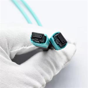
The Basics of Keying Positions
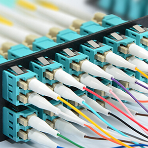
MTP®/MPO use the same termination patterns and connectors at the end of the cables. One of the signature identifiers with the cable connectors is the key. The key is oriented on either the top or bottom of the connector, and it allows technicians to orient the fiber arrangements at a glance. Depending on the polarity (which will be discussed in detail later), simply knowing the key positions is enough to properly install the cables.
Essentially, the “key up” position references the key notch being at the top of the cable with the first fiber position on the left. In the “key down” position, the first fiber position is on the right (with the key notch at the top).
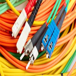
Fiber Strands and Color Code
MTP®/MPO cables are color-coded. This system makes it easy to arrange the fiber strands within the cable in order to conform to the standards that have been set. This ensures that cables are configured correctly and the cables provide the fast installation and efficiency they are designed to produce.
The color system assigns a unique color to each fiber position. The table below demonstrates the 12-fiber color system.
| Fiber # | 1 | 2 | 3 | 4 | 5 | 6 | 7 | 8 | 9 | 10 | 11 | 12 |
|---|---|---|---|---|---|---|---|---|---|---|---|---|
| Fiber # | 1 | 2 | 3 | 4 | 5 | 6 | 7 | 8 | 9 | 10 | 11 | 12 |
MTP®/MPO cables are color-coded
Polarity Types
Since MTP®/MPO cables conform to color-coded fiber standards, it’s easier to consider the possible polarity arrangements and how to use them. While many arrangements are theoretically possible, the industry mostly conforms to three normal polarities.

Type A is a straight connection.
| Side A | 1 | 2 | 3 | 4 | 5 | 6 | 7 | 8 | 9 | 10 | 11 | 12 |
|---|---|---|---|---|---|---|---|---|---|---|---|---|
| Side B | 1 | 2 | 3 | 4 | 5 | 6 | 7 | 8 | 9 | 10 | 11 | 12 |
Type B utilizes a reversed connection.
| Side A | 1 | 2 | 3 | 4 | 5 | 6 | 7 | 8 | 9 | 10 | 11 | 12 |
|---|---|---|---|---|---|---|---|---|---|---|---|---|
| Side B | 12 | 11 | 10 | 9 | 8 | 7 | 6 | 5 | 4 | 3 | 2 | 1 |
Type C is cross-pair oriented, also known as pair-flipped.
| Side A | 1 | 2 | 3 | 4 | 5 | 6 | 7 | 8 | 9 | 10 | 11 | 12 |
|---|---|---|---|---|---|---|---|---|---|---|---|---|
| Side B | 2 | 1 | 4 | 3 | 6 | 5 | 8 | 7 | 10 | 9 | 12 | 11 |
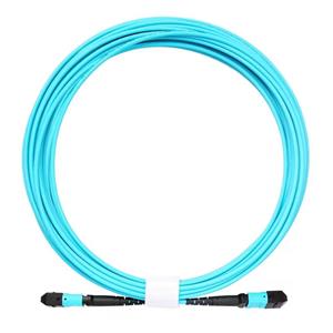
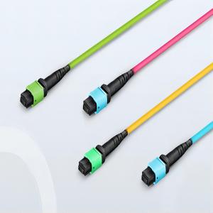
Trunk Cables
Trunk cables are denoted by using the same amount and type of connectors on both ends of the system. That means that no conversions or breakouts are needed between cables and transceivers.
In most cases, the trunk cables will use 8, 12, 16, 24, 32, 48 or 72 fibers. These work for optical modules that achieve 40GBASE, 100GBASE, 200GBASE and 400GBASE configurations.
The design of trunk cables makes them ideal for the highest-density use cases. They achieve the highest speeds in the industry right now with very low signal loss. As such, when transmission speeds are the most important consideration in a specific application, MTP trunk cables tend to be the optimal choice.
Breakout Cables
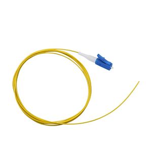
Breakout cables allow connections with different fiber pairings to communicate. They are primarily used to split or merge data flow. MTP breakout connectors can break into 4, 6, 8 or 12 connectors, and these connectors can be LC, SC, ST or other.
The most common conversions are MPO to 6 to LC (duplex)** and MPO to 4 LC (duplex). For example with MPO to 4 LC, using a 1 to 4 conversion, engineers can configure 4X10G or 4X25G connections. Either configuration can use the same breakout cable, which speaks to the strength of the pre-terminated designs used with MTP and MPO cables.
**Note: Many times, users will utilize an MPO-12 fiber for an MPO-8 application. In these case, 4 strands will submit signal, 4 strands will receive signal, and the middle 4 fiber lanes will not be used.
An emerging trend utilizes 1 to 8 conversion. This is good for 200G SR8 or 400G SR8 applications where one end matches to 25G SFP28 or 50G PAM SFP56. Using the breakout cables simplifies the topology by reducing the total amount of equipment needed for the conversions.
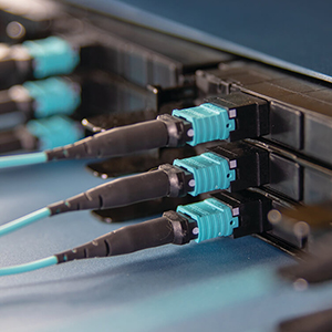
Use and Future of MTP®/MPO Cables in Data Centers
Pre-terminated cables save hours upon hours of labor at installation. For data centers that constantly need to scale up transmission speeds and capacity, MTP®/MPO cables provide the best solution. The costs saved with faster installation rack up quickly and often provide the best return on investment.
Summary
This efficiency is driving the bright future of MTP connectors. They are already becoming common in 400G and other high-speed fiber applications. As these speeds disseminate to more locations and become less exclusive, the easier installation and design needs of MTP cabling will do the heavy lifting.