FREE SHIPPING On Orders Over US$200
As fiber counts increase inside data centers, telecommunications rooms and enterprise networks, connector density becomes a practical design constraint.
A panel filled with large-format connectors occupies valuable rack space and can make patching, labeling and maintenance more difficult. The LC connector addresses this challenge with a compact 1.25 mm ferrule and a familiar latch mechanism.
Today, LC connectivity is widely used in:
- Data center equipment links
- Enterprise networks
- Telecommunications systems
- FTTH and PON networks
- DWDM equipment
- Test and measurement
- Fiber sensing
- Industrial communication systems
However, “LC” describes only the connector format. It does not independently define the fiber type, wavelength, polish, data rate, optical loss or cable construction.
An LC assembly must still be selected according to:
- Single-mode or multimode fiber
- Simplex or duplex operation
- UPC or APC polish
- Connector and adapter type
- Cable construction
- Optical-loss requirements
- Installation environment
- Transceiver interface
This guide explains the LC connector family and the main LC cables, adapters, attenuators and patch-panel configurations used in optical networks.
What Is an LC Fiber Optic Connector?
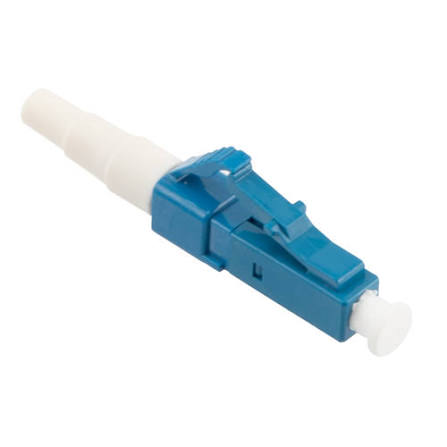
LC is a small-form-factor fiber optic connector developed by Lucent Technologies. It is commonly referred to as the Lucent Connector.
Its main features include:
- 1.25 mm ceramic ferrule
- Compact rectangular housing
- Latching retention mechanism
- Simplex and duplex configurations
- Single-mode and multimode compatibility
- UPC and APC polish options
- High-density panel installation
The 1.25 mm ferrule is half the diameter of the 2.5 mm ferrule used by connectors such as SC, FC and ST. This allows more LC ports to be installed within the same panel area.
The LC interface is standardized by specifications including IEC 61754-20 and TIA-604-10, also known as FOCIS-10.
LC Ferrule vs. Adapter Sleeve
The LC connector contains a precision ceramic ferrule that holds and centers the optical fiber.
When two LC connectors are mated through an adapter, a split alignment sleeve inside the adapter aligns the two ferrules.
These parts perform different functions:
| Component | Function |
|---|---|
| LC ferrule | Holds and positions the optical fiber |
| Split sleeve | Aligns two mating ferrules inside the adapter |
| Connector housing | Provides mechanical keying and retention |
| Latch | Keeps the connector secured in the adapter |
| Boot | Protects the cable-to-connector transition |
The ferrule is commonly made from zirconia ceramic. The adapter sleeve may also be ceramic, although some multimode or less demanding applications use metal sleeves.
How Does an LC Connection Work?
When an LC connector is inserted into an adapter:
- The connector housing establishes mechanical orientation.
- The ferrule enters the split alignment sleeve.
- The sleeve centers the two mating ferrules.
- The polished fiber end faces make physical contact.
- The latch secures the connector in place.
Optical performance depends on:
- Fiber-core alignment
- Ferrule concentricity
- End-face geometry
- Connector cleanliness
- Polish type
- Adapter-sleeve quality
- Mechanical stability
The connector does not increase network speed. It provides a low-loss optical interface between two fibers.
LC Simplex vs. LC Duplex
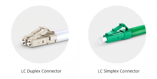
LC Simplex Connector
An LC simplex connection carries one optical fiber.
Typical applications include:
- BiDi transceivers
- PON and FTTH systems
- Fiber sensors
- Optical test equipment
- Single-channel laboratory links
- Monitoring ports
Simplex connectors provide greater routing flexibility because each fiber can be installed independently.
LC Duplex Connector
An LC duplex assembly places two LC connectors together with a clip or integrated housing.
The two fibers normally provide:
- One transmit path
- One receive path
Typical applications include:
- Duplex Ethernet optics
- Fibre Channel
- Server-to-switch links
- Storage networks
- Telecommunications equipment
- Data center patching
The duplex clip maintains spacing and polarity between the two fibers.
LC Simplex vs. Duplex Comparison
| Feature | LC Simplex | LC Duplex |
|---|---|---|
| Fiber count | One | Two |
| Common use | BiDi, PON, sensing and testing | Duplex Ethernet and equipment links |
| Polarity | Managed as an individual fiber | Maintained by duplex clip |
| Routing flexibility | Higher | Lower but easier to manage as a pair |
| Connector density | One port per fiber | Two fibers grouped together |
LC UPC vs. LC APC
LC connectors are available with different end-face polishes.
LC UPC
UPC means Ultra Physical Contact.
A UPC ferrule has a polished, curved end face designed to create physical contact between the two fiber cores.
Common characteristics include:
- Usually blue connector housing for single-mode products
- Low insertion loss
- Suitable return-loss performance for general digital communication
- Common use in Ethernet, data centers and test equipment
The UPC end face is not flat. Its controlled spherical geometry is an important part of achieving physical contact.
LC APC
APC means Angled Physical Contact.
An APC connector normally uses an approximately 8-degree angled end face. Reflected light is directed away from the fiber core, improving return-loss performance.
Common characteristics include:
- Usually green connector housing
- Lower back reflection than UPC
- Widely used in PON, CATV and reflection-sensitive systems
- Suitable for analog and wavelength-sensitive optical links
UPC and APC Compatibility
UPC and APC connectors must not be directly mated.
Their end-face geometries are different, and direct mating can cause:
- High insertion loss
- Poor return loss
- Unstable optical performance
- Scratched or damaged end faces
Adapters do not convert one polish into another. Both mating connectors must use compatible end-face types.
Typical LC Optical Performance
Specifications vary by product design and test method. Common single-mode patch-cord requirements may include:
| Parameter | Standard LC Assembly | Low-Loss LC Assembly |
|---|---|---|
| Insertion loss | Commonly ≤0.2–0.3 dB | May be specified below 0.15 dB |
| UPC return loss | Commonly ≥50 dB | Product-dependent |
| APC return loss | Commonly ≥60 dB | Product-dependent |
| Mating durability | Commonly hundreds of cycles | Product-dependent |
These should not be treated as universal values.
For a professional product specification, state:
- Maximum or typical value
- Test wavelength
- Fiber type
- Test method
- Connector polish
- Number of tested samples
Multimode products generally use different return-loss limits from single-mode assemblies.
Does LC Support 10G, 100G, 400G or 800G?
The LC connector itself does not define the transmission rate.
LC can be used with many duplex optical transceivers across a wide range of speeds, including selected:
- 1G
- 10G
- 25G
- 40G
- 100G
- 200G
- 400G
- 800G
However, not every transceiver at these speeds uses LC.
Depending on the optical standard, a module may instead use:
- MPO/MTP
- CS
- SN
- MDC
- Other multi-fiber or very-small-form-factor interfaces
For example:
- 10GBASE-SR commonly uses duplex LC.
- 40GBASE-LR4 commonly uses duplex LC.
- 40GBASE-SR4 normally uses MPO.
- 100GBASE-LR4 commonly uses duplex LC.
- 100GBASE-SR4 normally uses MPO.
- Some 400G FR4 and LR4 optics use duplex LC.
- Some 400G parallel-optics modules use MPO.
- Newer high-density optics may use CS, SN or other interfaces.
The cable must be selected according to the exact transceiver specification.
Main Types of LC Connectors
Standard LC Connector
The standard LC connector uses a conventional latch and boot.
It is suitable for:
- General patching
- Equipment connections
- Patch panels
- Telecommunications rooms
- Laboratory systems
LC Uniboot
An LC Uniboot cable combines two fibers inside one common jacket instead of using two separate cable legs.
Potential benefits include:
- Reduced cable volume
- Improved airflow
- Easier routing
- Cleaner high-density installations
Some Uniboot designs allow polarity reversal by opening or rotating part of the connector housing. The reversal method varies by manufacturer.
Uniboot does not change the optical standard. It is a cable-management construction used with compatible duplex-LC interfaces.
Pull-Tab LC
A pull-tab LC connector includes an extended extraction tab.
It is useful in high-density panels where technicians cannot easily grip the connector body.
Benefits may include:
- Easier insertion and removal
- Reduced disturbance to adjacent connectors
- Improved access in dense switch ports
- Less strain on the cable
LC Behind-the-Wall Connector
Behind-the-Wall, or BTW, LC connectors are compact terminations intended for internal equipment or backplane installation.
They are frequently used with:
- 900 μm buffered fiber
- Internal device wiring
- Transceiver assemblies
- Compact optical modules
Ruggedized LC
Ruggedized LC systems place a standard or modified LC optical interface inside a sealed protective housing.
Depending on the design, they may provide:
- Dust resistance
- Water resistance
- Mechanical protection
- Secure outdoor mating
- Vibration resistance
Examples include outdoor radio, antenna and industrial connector systems. Compatibility between ruggedized systems should not be assumed merely because they contain an LC ferrule.
LC Fiber Optic Cable Types
LC-to-LC Patch Cable
An LC-to-LC patch cable has LC connectors on both ends.
It may be configured as:
- Simplex
- Duplex
- Uniboot
- Single-mode
- Multimode
- UPC
- APC
- Armored
- Bend-insensitive
- Indoor or outdoor-rated
Typical uses include:
- Switch-to-server connections
- Patch-panel interconnections
- Transceiver patching
- Laboratory test cables
- Telecommunications equipment
LC Hybrid Patch Cable
A hybrid cable has an LC connector at one end and another connector type at the opposite end.
Common configurations include:
- LC to SC
- LC to FC
- LC to ST
- LC to E2000
- LC to MU
- LC to SMA
Hybrid cables are useful when connecting equipment with different optical interfaces.
The fiber type and polish must still be compatible at both ends.
LC Fiber Pigtail
An LC pigtail has:
- An LC connector on one end
- Unterminated fiber on the other
The bare end is normally fusion-spliced to a distribution cable inside:
- Patch panels
- Terminal boxes
- Optical distribution frames
- Splice closures
LC pigtails are available as single units or color-coded multi-fiber sets.
LC Uniboot Patch Cable
An LC Uniboot patch cable contains two fibers in one jacket.
It is most useful in:
- High-density server racks
- Switch fabrics
- Storage networks
- Installations where airflow and cable congestion matter
It should be used only with equipment that requires duplex LC connectivity.
Parallel SR4 applications normally require MPO-based cabling unless the optical module itself uses a duplex interface such as an appropriate BiDi design.
Armored LC Patch Cable
An armored LC cable includes an additional protective layer, such as a flexible stainless-steel tube.
It may improve resistance to:
- Crushing
- Rodents
- Accidental impact
- Repeated handling
Armor does not automatically make the cable:
- Waterproof
- Outdoor-rated
- Direct-burial-rated
- Plenum-rated
- Chemical-resistant
The complete cable specification must be checked.
Bend-Insensitive LC Patch Cable
Bend-insensitive fiber reduces macrobending loss when the cable is routed around tighter bends.
Common single-mode examples include G.657.A1 and G.657.A2 fiber.
These cables are useful in:
- High-density racks
- FTTH installations
- Compact enclosures
- Wall-mounted boxes
Bend-insensitive fiber still has a specified minimum bend radius. It should not be folded, pinched or sharply kinked.
Ultra-Low-Loss LC Patch Cable
Low-loss LC assemblies use tightly controlled ferrule, polishing and alignment processes.
They are valuable when a link contains:
- Multiple patch-panel connections
- Several adapters
- WDM components
- Limited receiver margin
- Strict channel-loss budgets
“Ultra-low-loss” should be supported by a stated maximum insertion-loss specification and individual test results.
A small connector-loss reduction does not translate directly into a fixed number of additional kilometers. Total reach also depends on fiber attenuation, dispersion, transmitter power, receiver sensitivity and engineering margin.
Mode-Conditioning LC Patch Cable
A mode-conditioning patch cord is used in specific legacy multimode applications, most commonly when a 1000BASE-LX/LH single-mode-style laser transmitter operates over installed OM1 or OM2 multimode fiber.
The transmit leg contains an offset single-mode-to-multimode launch designed to reduce differential-mode-delay problems.
Important points include:
- It is application-specific.
- The transmitter end must be installed in the correct orientation.
- It is not a general single-mode-to-multimode converter.
- It is not normally required for every OM3 or OM4 link.
- The exact transceiver and installed fiber must be checked.
MPO-to-LC Breakout Cable
An MPO-to-LC breakout cable has:
- One MPO connector
- Multiple LC simplex or duplex connectors
Common applications include:
- 40G to four 10G breakout
- 100G to four 25G breakout
- High-density trunk distribution
- Parallel-optics testing
- Patch-panel fan-out
The cable must match:
- Active fiber count
- MPO gender
- Polarity
- Key orientation
- Fiber type
- Connector polish
- Transceiver lane mapping
A passive breakout cable separates optical lanes; it does not independently convert one data rate into another.
LC Fiber Adapters
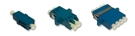
An LC adapter aligns and joins two LC connectors.
The internal split sleeve centers the ferrules.
LC Simplex Adapter
A simplex adapter connects one fiber channel.
Typical uses include:
- PON panels
- BiDi systems
- Test equipment
- Fiber distribution frames
LC Duplex Adapter
A duplex adapter connects two LC channels in one housing.
It is widely used for duplex Ethernet and telecommunications links.
LC Quad Adapter
A quad adapter contains four simplex LC channels, normally presented as two duplex pairs or four individual ports.
It can increase panel density while retaining familiar LC connectivity.
Flanged and Flangeless Adapters
Flanged Adapter
A flanged adapter is secured to the panel using screws or clips.
It provides strong mechanical retention.
Flangeless Adapter
A flangeless adapter normally snaps into a correctly sized panel opening.
It can provide a cleaner front-panel appearance and faster installation.
Shuttered LC Adapter
A shuttered adapter contains an internal or external dust-protection mechanism.
Potential benefits include:
- Reduced dust entry
- Reduced accidental contact with the ferrule
- Improved unused-port protection
The shutter does not eliminate the need to inspect and clean the connector before mating.
Hybrid LC Adapter
A hybrid adapter connects different connector formats, such as:
- LC to SC
- LC to FC
- LC to ST
A hybrid adapter changes the mechanical interface but does not convert fiber mode or end-face polish.
LC Fiber Optic Attenuators
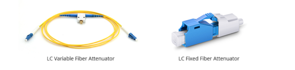
An LC attenuator introduces controlled optical loss into an LC link.
Fixed LC Attenuator
A fixed LC attenuator provides a preset attenuation value, such as:
- 1 dB
- 3 dB
- 5 dB
- 10 dB
- 15 dB
- 20 dB
A common plug-style design has:
- LC male connector at one end
- LC female interface at the other
It can be inserted directly in front of an optical receiver or inside a patch panel.
In-Line LC Attenuator
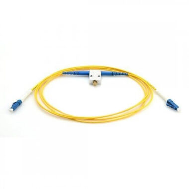
An in-line attenuator is built into a fiber cable or compact optical component.
It may be suitable for permanent installations where the attenuator should not project from the equipment port.
Variable Optical Attenuator
A VOA provides adjustable loss.
Some laboratory and rack-mounted VOAs use LC adapters, but the attenuation mechanism is contained inside the instrument or module rather than in the LC connector itself.
VOAs are used for:
- Receiver-sensitivity testing
- BER testing
- Optical-margin analysis
- Loss simulation
- Automated optical testing
Selecting an LC Attenuator
Confirm:
- Required attenuation
- Operating wavelength
- Single-mode or multimode fiber
- UPC or APC polish
- Attenuation tolerance
- Return loss
- Maximum input power
- Environmental range
Calculate the attenuation from actual transmitter power, link loss and receiver limits rather than selecting a common value arbitrarily.
LC Patch Panels
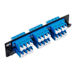
LC patch panels organize, protect and present LC fiber connections.
Fixed LC Patch Panel
A fixed panel has a predetermined number of LC adapter openings.
It is suitable for:
- Small equipment rooms
- Stable fiber counts
- Cost-sensitive projects
- Simple patching requirements
Sliding LC Patch Panel
A sliding or draw-out panel allows the tray to move forward for access to:
- Splice trays
- Pigtails
- Cable entries
- Rear adapters
This can simplify installation and maintenance in crowded racks.
Modular Cassette Panel
A modular chassis accepts replaceable cassettes or adapter plates.
Benefits include:
- Incremental expansion
- Mixed connector formats
- MPO-to-LC conversion
- Easier moves and changes
- Replaceable modules
High-Density LC Panel
High-density LC panels use compact adapters, staggered rows or pull-tab connectors to increase port count.
When evaluating panel density, distinguish between:
- LC simplex ports
- LC duplex ports
- Total fiber count
For example, 72 LC duplex ports represent 144 individual fibers.
Density claims should always define which measurement is being used.
Pre-Terminated MPO-to-LC Panel
A pre-terminated panel uses MPO trunks or internal MPO-to-LC cassettes to present LC ports at the front.
Potential benefits include:
- Faster installation
- Factory-controlled polarity
- Reduced field termination
- Test documentation
- Modular deployment
The total optical loss must include the internal MPO and LC connection points.
Selecting an LC Patch Panel
Consider:
- Rack size
- Fiber count
- Simplex or duplex ports
- Adapter type
- Splice or pre-terminated installation
- Cable-entry direction
- Bend-radius management
- Labeling
- Future expansion
- Maximum acceptable link loss
- Front or rear maintenance access
Choosing the Right LC Product
| Selection Factor | Questions to Confirm |
|---|---|
| Fiber type | OS2, OM1, OM2, OM3, OM4 or OM5? |
| Fiber count | Simplex, duplex or multi-fiber fan-out? |
| Polish | UPC or APC? |
| Connector ends | LC-to-LC or hybrid? |
| Cable construction | Standard, Uniboot, armored, pigtail or breakout? |
| Wavelength | 850, 1310, 1490, 1550 nm or another range? |
| Data interface | Which exact transceiver is being connected? |
| Insertion loss | Standard or low-loss requirement? |
| Return loss | Is the application reflection-sensitive? |
| Jacket | PVC, LSZH, OFNR, OFNP, PE or another rating? |
| Environment | Indoor, outdoor, industrial or laboratory? |
| Panel type | Fixed, sliding, modular or high-density? |
| Documentation | Are IL, RL, polarity or end-face reports required? |
LC Connector Cleaning and Inspection
Contamination is one of the most common causes of fiber connection problems.
Use an inspect-clean-inspect procedure:
- Inspect the connector end face with an appropriate fiber microscope.
- Clean it if contamination is visible.
- Inspect it again before mating.
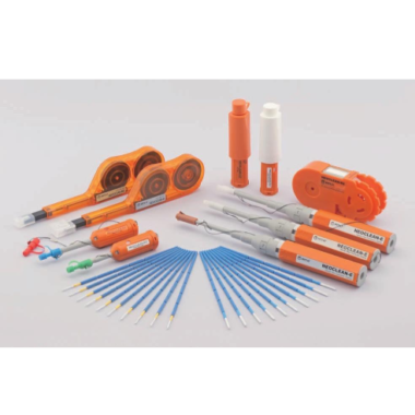
Suitable cleaning methods may include:
- LC one-click cleaner
- Clean, lint-free cassette cleaner
- Lint-free wipe with an approved fiber-cleaning solvent
- Properly sized adapter cleaner
Avoid:
- Touching the ferrule end face
- Using ordinary household tissues
- Reusing dirty cleaning areas
- Mating a dirty connector
- Using excessive liquid
- Cleaning while a high-power source is active
Standard consumer alcohol wipes may leave residue or fibers and are not the preferred general method.
Common LC Selection Mistakes
Assuming Every LC Product Has the Same Loss
Loss depends on ferrule quality, fiber type, polish, alignment and test method.
Mating UPC and APC Connectors
Their geometries are incompatible.
Selecting by Data Rate Alone
Different optical standards at the same rate can use different connector types.
Using an LC Cable for an MPO Transceiver
An adapter cannot passively convert a parallel MPO interface into duplex LC without an appropriate breakout architecture and compatible optics.
Treating Uniboot as a Parallel-Optics Cable
Uniboot contains two fibers and is intended for duplex-LC interfaces.
Confusing Port Count With Fiber Count
One duplex LC port represents two fibers.
Relying Only on Connector Color
Colors are useful identifiers but may be customized. Check the printed cable marking and product specification.
Ignoring End-Face Inspection
A connector can be correctly specified and still fail because of contamination.
Frequently Asked Questions
What is an LC-to-LC fiber patch cable?
It is a fiber optic cable terminated with LC connectors at both ends.
It may be simplex, duplex, Uniboot, single-mode or multimode.
What does LC stand for?
LC is commonly expanded as Lucent Connector and was developed by Lucent Technologies.
What is the difference between LC single-mode and multimode cables?
Single-mode LC cables normally use OS1, OS2 or another single-mode fiber and are used with compatible single-mode optics.
Multimode LC cables use OM1, OM2, OM3, OM4 or OM5 fiber and are used with compatible multimode optics.
The LC connector housing alone does not determine the fiber type.
What is an LC duplex connector?
It consists of two LC connectors joined together so that two fibers can be handled as one transmit-and-receive pair.
Can LC connect directly to SC or FC?
No.
A hybrid patch cable or hybrid adapter is required.
What transmission speed does LC support?
LC does not have one fixed speed rating.
Supported speed depends on the optical transceiver, wavelength, fiber type and link budget. LC is used by many duplex optical interfaces from low-speed systems through selected 400G and 800G applications.
Can LC UPC connect to LC APC?
No.
Their end-face geometries are incompatible.
What are common LC patch-cable lengths?
Common stocked lengths may include:
- 1 m
- 2 m
- 3 m
- 5 m
- 10 m
The correct length should minimize excess slack without placing tension on the connectors.
How should an LC connector be cleaned?
Inspect it first, then use an LC-compatible one-click cleaner, cassette cleaner or approved lint-free cleaning method. Inspect it again before mating.
Is LC better than SC?
LC provides higher port density because of its smaller ferrule and housing.
SC may be easier to handle in lower-density installations. The appropriate connector depends on equipment compatibility, density, environment and maintenance requirements.
Conclusion
LC has become one of the most widely used fiber optic connector formats because it combines compact dimensions, familiar latching and broad availability across single-mode and multimode systems.
Its 1.25 mm ferrule supports higher panel density than traditional 2.5 mm connector formats, but LC should not be treated as one uniform product.
A complete LC solution may include:
- Simplex or duplex connectors
- UPC or APC end faces
- Standard or Uniboot patch cords
- Pigtails
- Armored cables
- MPO-to-LC breakout assemblies
- Adapters
- Fixed attenuators
- Modular or high-density patch panels
Correct selection requires matching the LC assembly to the fiber type, transceiver interface, wavelength, polish, optical-loss budget and installation environment.
Fiber-Life supplies configurable LC fiber optic products, including patch cables, pigtails, adapters, attenuators, breakout assemblies and patch-panel solutions. Fiber type, connector polish, cable construction, length, jacket, polarity and test requirements can be specified according to the application.