FREE SHIPPING On Orders Over US$200
Single-mode and multimode fiber are both widely used in modern optical networks, but they are designed for different transmission requirements.
Multimode fiber is commonly associated with short-reach data center and enterprise connections, while single-mode fiber is used for campus, telecommunications and long-distance links. That distinction is useful, but it is not sufficient for making a purchasing decision.
A 100-meter data center link may support either fiber type. Likewise, choosing single-mode fiber does not automatically mean the complete system will be more expensive, and choosing multimode fiber does not guarantee lower cost.
The correct decision depends on:
- Transmission speed
- Required distance
- Optical transceiver type
- Existing cabling infrastructure
- Connector and fiber-count requirements
- Future upgrade plans
- Total installed cost
This guide explains the key differences between single-mode and multimode fiber and provides a practical framework for selecting the appropriate cable.
Single-Mode vs. Multimode Fiber at a Glance
| Feature | Single-Mode Fiber | Multimode Fiber |
|---|---|---|
| Common categories | OS1, OS2 | OM1, OM2, OM3, OM4, OM5 |
| Typical core diameter | Approximately 9 μm | 50 μm or legacy 62.5 μm |
| Cladding diameter | 125 μm | 125 μm |
| Number of guided modes | One fundamental spatial mode under specified operating conditions | Multiple spatial modes |
| Common wavelengths | 1310 nm, 1550 nm | 850 nm, 1300 nm; OM5 also supports specified wideband performance |
| Common light source | Laser | LED or VCSEL |
| Typical reach | From hundreds of meters to many kilometers | Usually tens to hundreds of meters at high data rates |
| Main dispersion concern | Chromatic dispersion and polarization-mode dispersion | Modal dispersion and chromatic dispersion |
| Common applications | Telecom, PON, campus backbone, metro and long-reach data links | Data centers, equipment rooms, enterprise LANs and short-reach links |
| Typical jacket identification | Yellow for many indoor OS1/OS2 assemblies | Orange, aqua, violet or lime green depending on category |
| Common connector formats | LC, SC, FC, ST, MPO and others | LC, SC, ST, MPO and others |
What Is Single-Mode Fiber?

Single-mode fiber has a relatively small core, typically around 9 μm, surrounded by 125 μm cladding.
At the intended operating wavelength, it guides primarily one fundamental spatial mode. Eliminating multiple propagation modes prevents the differential modal delay that limits multimode transmission distance.
Common single-mode categories include:
OS1 Fiber
OS1 is generally associated with indoor, tight-buffered single-mode cable. It is used in building backbones and other controlled indoor environments.
OS2 Fiber
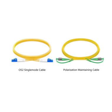
OS2 is commonly used for low-loss indoor, outdoor and indoor/outdoor installations. It is widely deployed in:
- Telecommunications networks
- Data center interconnections
- Campus backbones
- Passive optical networks
- Metropolitan-area networks
- Long-distance Ethernet links
- Industrial communication systems
OS2 is normally the preferred category for new general-purpose single-mode infrastructure.
What Is Multimode Fiber?

Multimode fiber has a larger core that allows multiple optical modes to propagate simultaneously.
The larger core simplifies optical coupling and supports cost-effective VCSEL-based transceivers. However, different modes do not arrive at the receiver at exactly the same time. This pulse spreading is known as modal dispersion and limits the achievable distance at higher data rates.
The main multimode categories are:
OM1
OM1 uses a 62.5/125 μm geometry and was designed primarily for legacy LED-based networks.
It remains installed in many older buildings but provides limited reach for modern high-speed Ethernet.
OM2
OM2 uses a 50/125 μm core and offers better bandwidth than OM1, but it is also considered a legacy choice for most new high-speed installations.
OM3
OM3 is a laser-optimized 50/125 μm multimode fiber designed for 850 nm VCSEL transmission.
It is widely used for 10G, 25G, 40G and 100G short-reach applications.
OM4
OM4 is also a laser-optimized 50/125 μm fiber but provides higher modal bandwidth than OM3. It can support longer standardized distances for many 850 nm Ethernet applications.
For example, common 10GBASE-SR modules support up to 300 m over OM3 and 400 m over OM4.
OM5
OM5 is a wideband 50/125 μm multimode fiber.
At 850 nm, OM5 has the same minimum effective modal bandwidth as OM4: 4,700 MHz·km. OM5 additionally specifies at least 2,470 MHz·km at 953 nm, making it suitable for shortwave wavelength-division multiplexing applications.
OM5 is not automatically faster than OM4 in conventional 850 nm applications. Its primary advantage appears when the optical module actually uses multiple short wavelengths.
1. Core Diameter and Light Propagation

The most visible physical difference is core diameter:
- Single-mode: approximately 9/125 μm
- OM1 multimode: 62.5/125 μm
- OM2, OM3, OM4 and OM5: 50/125 μm
The larger multimode core allows multiple propagation paths. Some paths are longer than others, causing the optical pulses to spread as they travel.
Single-mode fiber avoids this modal dispersion because it guides only the fundamental mode under normal operating conditions.
However, it is inaccurate to say that single-mode light simply travels in a perfectly straight line while multimode light repeatedly reflects from the cladding. Both are dielectric waveguides, and their behavior is more accurately described by guided optical modes.
2. Wavelength and Light Source
Single-Mode Fiber
Common single-mode operating wavelengths include:
- 1310 nm
- 1490 nm
- 1550 nm
- 1625 nm for some monitoring and specialized applications
Single-mode systems normally use laser-based transmitters.
Different transceiver classes may use one wavelength, two bidirectional wavelengths or multiple wavelengths through CWDM or DWDM technology.
Multimode Fiber
Common multimode operating wavelengths include:
- 850 nm
- 1300 nm
- Multiple wavelengths between approximately 850 and 950 nm for compatible wideband systems
Modern high-speed multimode transceivers generally use 850 nm VCSELs.
OM5 supports wideband applications such as SWDM, but conventional OM3 and OM4 systems still operate primarily around 850 nm.
3. Attenuation and Dispersion
Attenuation describes the reduction in optical power as light travels through the fiber. It is normally expressed in dB/km.
Typical values are often approximately:
| Fiber Type | Common Test Wavelength | Representative Attenuation |
|---|---|---|
| Multimode | 850 nm | Around 3.0 dB/km |
| Multimode | 1300 nm | Around 1.0 dB/km |
| Single-mode | 1310 nm | Around 0.35–0.40 dB/km |
| Single-mode | 1550 nm | Around 0.20–0.25 dB/km |
Actual specifications depend on the fiber manufacturer, cable construction and applicable standard.
Single-mode fiber generally has lower attenuation at its common operating wavelengths, but attenuation is not the only factor affecting reach.
Modal Dispersion
Modal dispersion occurs in multimode fiber because multiple modes arrive at different times.
It is one of the main reasons that multimode transmission distance decreases as data rate increases.
Chromatic Dispersion
Chromatic dispersion occurs because different optical wavelengths travel at slightly different speeds.
It affects both single-mode and multimode systems, although its significance depends on the light source, spectral width, transmission rate and distance.
Polarization-Mode Dispersion
Polarization-mode dispersion can affect high-speed single-mode links, particularly over long distances.
Single-mode fiber therefore does not have literally unlimited bandwidth. It eliminates modal dispersion, but the complete link remains limited by fiber dispersion, attenuation, transceiver electronics, modulation and receiver performance.
4. Bandwidth
Multimode fiber is commonly specified using modal bandwidth, expressed in MHz·km.
| Multimode Category | Common Core Size | Minimum EMB at 850 nm | Additional Wideband Specification |
|---|---|---|---|
| OM1 | 62.5 μm | Not normally specified by EMB in the same way as OM3–OM5 | None |
| OM2 | 50 μm | Legacy multimode specification | None |
| OM3 | 50 μm | 2,000 MHz·km | None |
| OM4 | 50 μm | 4,700 MHz·km | None |
| OM5 | 50 μm | 4,700 MHz·km | 2,470 MHz·km at 953 nm |
OM5 should not be described as having a general bandwidth of 28,000 MHz·km. Its standardized distinguishing values are its effective modal bandwidth requirements at 850 and 953 nm.
Single-mode fiber is generally not compared through a simple MHz·km modal-bandwidth rating because modal dispersion is not its primary limitation.
5. Transmission Distance
Transmission distance is determined by the complete optical standard, not by the fiber category alone.
The same OS2 cable may support 10 km, 40 km or 80 km depending on the transceiver. Likewise, the same OM4 cable may support 400 m at 10G but only 100 m at 100GBASE-SR4.
The table below shows common examples.
| Ethernet Application | OM1 | OM2 | OM3 | OM4 / OM5 | Common OS2 Alternative |
|---|---|---|---|---|---|
| 1000BASE-SX | Up to 275 m | Up to 550 m | Up to 550 m | Up to 550 m | 1000BASE-LX/LH: module-dependent, commonly several kilometers |
| 10GBASE-SR | Up to 33 m | Up to 82 m | Up to 300 m | Up to 400 m | 10GBASE-LR: up to 10 km |
| 25GBASE-SR | Not normally recommended | Not normally recommended | Up to 70 m | Up to 100 m | 25GBASE-LR: up to 10 km |
| 40GBASE-SR4 | Not normally supported | Not normally supported | Up to 100 m | Up to 150 m | 40GBASE-LR4: up to 10 km |
| 100GBASE-SR4 | Not normally supported | Not normally supported | Up to 70 m | Up to 100 m | 100GBASE-LR4: up to 10 km |
Cisco’s published module specifications confirm 10GBASE-SR reaches of 300 m on OM3 and 400 m on OM4; 25GBASE-SR reaches of 70 m on OM3 and 100 m on OM4 or OM5; 40GBASE-SR4 reaches of 100 m on OM3 and 150 m on OM4; and 100GBASE-SR4 reaches of 70 m on OM3 and 100 m on OM4.
These are representative standardized or vendor-supported values. Actual design limits must be verified against the exact transceiver datasheet, FEC requirement, connector count and channel-loss budget.
Extended-reach, bidirectional and SWDM modules may support different distances. Their results should not be combined with standard SR or SR4 values in the same table without clearly identifying the transceiver type.
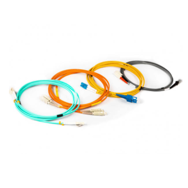
6. Fiber Jacket Colors
Common indoor patch-cord and cable colors include:
| Fiber Category | Common Jacket Color |
|---|---|
| OS1 / OS2 | Yellow |
| OM1 | Orange |
| OM2 | Orange |
| OM3 | Aqua |
| OM4 | Aqua; violet is also used by some manufacturers |
| OM5 | Lime green |
Panduit documentation identifies yellow for single-mode, orange for OM1/OM2, aqua for OM3/OM4 and lime green for OM5. Corning also offers violet as an OM4 identification option in some product families.
Color should be treated as a convenient visual identifier, not definitive proof of fiber type.
Exceptions are common:
- Outdoor cables may use black UV-resistant jackets.
- Manufacturers may offer customized colors.
- Data centers may use colors to identify networks or services.
- Connector body color and cable jacket color may follow different conventions.
Always verify the printed cable marking, part number and datasheet.
7. Connector Types and Polish

Single-mode and multimode fiber can use many of the same mechanical connector formats, including:
- LC
- SC
- FC
- ST
- E2000
- MPO/MTP
An LC connector is not inherently single-mode or multimode. Its ferrule, fiber, polish and performance specification determine the application.
Multimode Connectors
Multimode assemblies commonly use UPC or PC-type end faces and are often identified by beige, black, aqua, violet or lime-green components, depending on fiber category and manufacturer.
Single-Mode Connectors
Single-mode assemblies commonly use:
- UPC polish, often with blue connector bodies
- APC polish, often with green connector bodies
UPC and APC connectors should not be directly mated because their end-face geometries differ. Doing so can cause excessive insertion loss, poor return loss and connector damage.
8. Fiber Count and Cabling Architecture
Fiber type and fiber count are separate decisions.
A duplex LC link normally uses two fibers:
- One transmit fiber
- One receive fiber
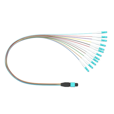
Parallel optical systems may use MPO connectors and multiple active fibers.
For example:
- 40GBASE-SR4 normally uses eight active multimode fibers.
- 100GBASE-SR4 normally uses eight active multimode fibers.
- Some 400G multimode interfaces use eight or sixteen active fibers.
- Single-mode CWDM and LR4 systems may carry several wavelengths over only two fibers.
A higher-speed link therefore does not always require more fibers. The required count depends on whether the transceiver uses parallel optics, wavelength multiplexing or bidirectional transmission.
9. Single-Mode vs. Multimode Cost
Cost should be evaluated at the system level rather than by comparing fiber cable or transceiver prices in isolation.
Fiber Cable Cost
The bare single-mode fiber component is often priced similarly to, or lower than, high-performance OM4 or OM5 fiber.
However, the cable price also depends on:
- Fiber count
- Jacket rating
- Armor
- Indoor or outdoor construction
- Connector type
- Polarity
- Testing requirements
- Cable length
- Production quantity
It is therefore inaccurate to assume that single-mode cable is always more expensive.
Transceiver Cost
Short-reach VCSEL-based multimode optics are often economically attractive for data center links.
Single-mode transceivers may require more complex laser, wavelength-control and alignment technologies. However, the price difference varies significantly by speed, reach, form factor, market volume and vendor.
A fair comparison must use modules designed for comparable reach and functionality.
For example, comparing:
- 40GBASE-SR4 at 100–150 m
with:
- 40GBASE-LR4 at 10 km
does not demonstrate the inherent price difference between fiber types. It compares a short-reach parallel module with a wavelength-multiplexed long-reach module.
Installation Cost
Installation cost may include:
- Cable and transceiver cost
- Patch panels and cassettes
- MPO or LC connectivity
- Splicing and termination
- Testing
- Pathway space
- Labor
- Future replacement work
- Spare-parts inventory
Multimode may provide the lowest initial cost for a short-reach link. Single-mode may provide better lifecycle economics when distances are longer or when repeated multimode upgrades would require recabling.
Total Cost of Ownership
A proper comparison should consider:
- Current transmission rate
- Planned upgrade rate
- Expected service life
- Cable replacement difficulty
- Transceiver roadmap
- Power consumption
- Port density
- Number of required fibers
- Operational and testing costs
Hard-coded transceiver prices should generally be avoided in an evergreen technical article because they quickly become outdated.
10. Typical Applications
Single-Mode Fiber Applications
Single-mode fiber is commonly selected for:
- Carrier networks
- FTTH and PON systems
- Campus backbones
- Metropolitan-area networks
- Long-reach data center interconnects
- Telecommunications transmission
- Industrial networks
- CCTV and security backbones
- DWDM and CWDM systems
- Laboratory and sensing applications
Multimode Fiber Applications
Multimode fiber is commonly selected for:
- Data center equipment connections
- Server-to-switch links
- Switch uplinks within a building
- Enterprise LAN backbones
- Storage-area networks
- Short-reach high-speed Ethernet
- Equipment rooms
- Factory and building automation
- Legacy FDDI and Fibre Channel installations
Which Fiber Should You Choose?
There is no universally superior fiber type. The appropriate choice depends on the link design.
Choose Multimode Fiber When:
- The link is within a building or data center.
- The required distance is within the selected SR transceiver limit.
- Lower-cost short-reach optics are a priority.
- OM3 or OM4 infrastructure is already installed.
- Parallel MPO connectivity fits the cabling design.
- The expected upgrade path is clearly supported by the selected multimode category.
For most new conventional multimode installations, OM4 is generally more practical than OM1 or OM2.
OM5 should be considered when compatible wideband, BiDi or SWDM technologies form part of the network plan. It should not be selected merely because its category number is higher.
Choose Single-Mode Fiber When:
- The link exceeds multimode distance limits.
- Building-to-building or campus connectivity is required.
- The installed cable will be difficult or expensive to replace.
- Long-term scalability is a priority.
- Duplex fiber connectivity is preferred for high data rates.
- CWDM, DWDM or PON technology is required.
- The network may need several kilometers of reach.
- A broad range of current and future optics is required.
Consider Installing Both When:
Some facilities install both OS2 and OM4 trunks in strategic locations.
This can provide:
- Short-reach multimode options
- Long-reach single-mode options
- Flexibility for different equipment generations
- Reduced risk when future transceiver requirements are uncertain
The additional initial cost must be weighed against pathway space and expected future requirements.
Practical Selection Examples
Example 1: 10G Link Across a Data Center
Required distance: 120 m.
Both OM3 and OM4 can support a conventional 10GBASE-SR link at this distance. OM4 may provide more upgrade flexibility, while OS2 may be considered if long-term migration to single-mode optics is planned.
Example 2: 25G Server Connection at 80 m
Standard 25GBASE-SR generally supports:
- 70 m over OM3
- 100 m over OM4 or OM5
OM4 or OM5 would therefore be appropriate. OM3 would not provide the standard 80 m reach for this application.
Example 3: 100G Link at 90 m
A conventional 100GBASE-SR4 link can support:
- Up to 70 m over OM3
- Up to 100 m over OM4
OM4 is appropriate if an MPO-based parallel multimode architecture is acceptable. A duplex single-mode solution may also be evaluated depending on transceiver availability and future plans.
Example 4: Connection Between Buildings at 800 m
Single-mode OS2 is the more appropriate choice.
Although specialized multimode modules may support extended distances in some cases, OS2 provides a broader selection of standardized medium- and long-reach transceivers.
Example 5: New Campus Backbone
Even when the initial links are relatively short, OS2 is usually preferable because campus pathways are difficult to replace and future distance or speed requirements may change.
Can Single-Mode and Multimode Fiber Be Mixed?
They should not normally be connected directly.
The core sizes and launch conditions are different. Directly coupling a multimode transmitter and single-mode fiber, or a single-mode transmitter and multimode fiber, can cause:
- Excessive insertion loss
- Unstable modal behavior
- Reduced transmission distance
- Increased bit-error rate
- Link failure
Limited Exception: 1000BASE-LX Over Multimode Fiber
Some 1000BASE-LX/LH transceivers are designed to operate over both single-mode and multimode fiber.
When used with legacy OM1 or OM2 cable, a mode-conditioning patch cord may be required to create an offset launch and reduce differential-mode-delay problems. Cisco specifically requires such patch cords for defined LX/LH, LX4 and LRM applications over legacy multimode fiber.
This is a standards-defined compatibility method, not a general rule that single-mode modules can be used freely with multimode cable.
Media Conversion
A media converter, switch or optical transport device can convert between separate single-mode and multimode links.
In this case, the two fiber types are not directly spliced together as one continuous passive optical channel. Active equipment receives and retransmits the signal using the correct optical interface on each side.
Common Selection Mistakes
Choosing Fiber Before Choosing the Optical Standard
“100G” alone is not enough information.
100G interfaces may use:
- Duplex LC multimode
- Parallel MPO multimode
- Duplex LC single-mode
- Parallel MPO single-mode
- Different reaches and wavelength plans
The exact transceiver must be selected before finalizing fiber type and count.
Assuming Single-Mode Is Always More Expensive
Single-mode optics may cost more for some short-reach applications, but the fiber cable itself is not necessarily more expensive. Lifecycle cost may favor OS2 when recabling would be difficult.
Assuming Multimode Is Always Easier
The larger core can simplify optical coupling, but MPO polarity, multiple parallel lanes and high-density connectors can make some multimode systems operationally complex.
Selecting OM5 Without Compatible Optics
Conventional 850 nm transceivers generally receive no standardized distance benefit from OM5 compared with OM4.
OM5’s wideband advantages require compatible optical technology.
Relying Only on Jacket Color
Cable color may be customized and outdoor cables are often black. Always check the printed marking and product specification.
Ignoring the Link-Loss Budget
Distance is not the only limitation.
Every connection introduces loss, including:
- Connector pairs
- MPO cassettes
- Splices
- Splitters
- Patch panels
- Conversion modules
The complete channel must remain within the transceiver’s optical budget.
Frequently Asked Questions
Is single-mode fiber faster than multimode fiber?
Fiber type alone does not define the data rate.
Both fiber types can support high-speed transmission when used with compatible transceivers. Single-mode generally supports greater distance and a broader range of long-reach technologies.
Is multimode fiber better for data centers?
Multimode fiber is widely used for short-reach data center links because VCSEL-based optics can be cost-effective.
Single-mode is increasingly used where longer reach, duplex connectivity or extended upgrade flexibility is required. The correct choice depends on the architecture.
Can LC connectors be used with both fiber types?
Yes.
LC describes the connector format, not the fiber mode. LC assemblies are available for OS2, OM1, OM2, OM3, OM4 and OM5.
Can I connect an APC connector to a UPC adapter?
The adapter sleeve itself may accept the connector mechanically, but APC and UPC connector end faces should not be mated to each other.
Both sides of a connection must use compatible polish types.
Is OS2 better than OS1?
OS2 generally provides lower attenuation and broader indoor/outdoor applicability, making it the more common choice for new general-purpose single-mode infrastructure.
Is OM4 better than OM3?
OM4 provides higher modal bandwidth and longer reach in many 850 nm applications.
However, OM3 remains suitable when the required speed and distance fall within its specifications.
Is OM5 better than OM4?
OM5 provides additional standardized bandwidth at 953 nm and is designed for wideband multimode applications.
For conventional 850 nm Ethernet, OM5 and OM4 often have the same supported distance.
Can a multimode transceiver operate over single-mode fiber?
Generally, no.
The launch conditions and optical design are different. Use the fiber type specified by the transceiver manufacturer.
Which is more future-ready, OS2 or OM5?
OS2 generally provides greater reach and a wider selection of optical technologies.
OM5 may be valuable where the network roadmap specifically includes compatible wideband multimode optics. Neither should be selected solely on its category name.
Conclusion
Single-mode and multimode fiber serve different network requirements.
Multimode fiber provides an efficient solution for short-reach enterprise and data center links, particularly when cost-effective VCSEL-based optics and existing OM3 or OM4 infrastructure are available.
Single-mode fiber offers significantly greater transmission distance and supports a broad range of duplex, bidirectional and wavelength-multiplexed technologies. It is commonly preferred for telecommunications, campus backbones, long-reach data center links and infrastructure that will be difficult to replace.
The final decision should be based on:
- Exact transceiver standard
- Data rate
- Required distance
- Fiber count
- Connector architecture
- Channel-loss budget
- Existing infrastructure
- Upgrade strategy
- Total cost of ownership
Fiber-Life supplies customizable OS2, OM1, OM2, OM3, OM4 and OM5 fiber optic cable assemblies, including LC, SC, FC, ST and MPO/MTP configurations. Fiber type, connector polish, cable length, jacket material, polarity and testing requirements can be configured for data center, enterprise, telecommunications and laboratory applications.