FREE SHIPPING On Orders Over US$200
As data centers migrate toward higher port densities and faster transmission rates, traditional single-fiber cabling can create practical challenges. Large numbers of individual patch cords consume valuable rack space, increase installation time and make cable management more difficult.
MPO cabling addresses these challenges by combining multiple optical fibers within a single compact connector. It is widely used in structured cabling systems, parallel-optics links and high-density backbone connections supporting 40G, 100G, 400G and other high-speed network architectures.
However, selecting the right MPO cable requires more than choosing a fiber count. Connector gender, polarity, fiber type, end-face geometry and insertion-loss performance must all match the intended application.
This guide explains how MPO cabling works, the main benefits it offers and the factors that should be evaluated before deployment.
What Is an MPO Cable?
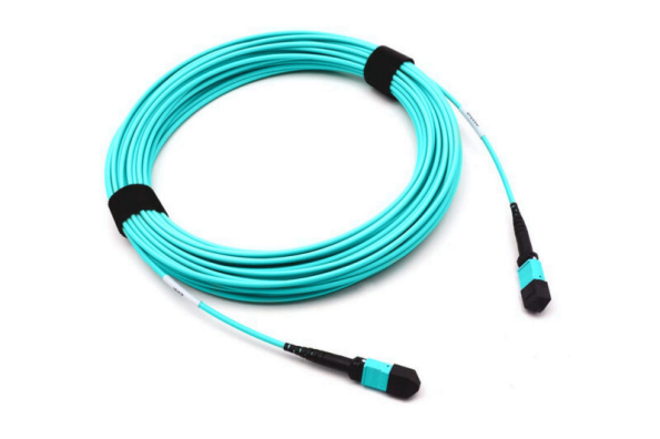
MPO stands for Multi-Fiber Push-On. An MPO connector contains multiple optical fibers arranged in one or more rows inside a rectangular ferrule.
Unlike an LC or SC connector, which normally terminates one fiber, an MPO connector can terminate multiple fibers within a single interface.
Common MPO configurations include:
- 8 fibers
- 12 fibers
- 16 fibers
- 24 fibers
- 32 fibers
- Higher customized fiber counts
The appropriate fiber count depends on the transceiver interface, transmission method and cabling architecture.
For example:
- MPO-8 and MPO-12 assemblies are commonly used for 40G and 100G parallel-optics links.
- MPO-16 assemblies may be used with certain 400G SR8 applications.
- MPO-24 assemblies are frequently used in high-density backbone cabling and cassette-based distribution systems.
MPO assemblies are generally supplied as factory-terminated and tested products. This reduces the need for field termination and can provide more consistent optical performance.
MPO vs. MTP: What Is the Difference?
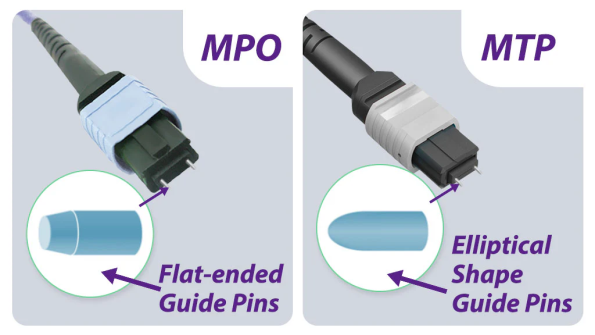
MPO is the generic interface type defined by international standards. MTP is a registered product brand of US Conec designed as an enhanced MPO connector.
An MTP connector is therefore an MPO-compatible connector, but not every MPO connector is an MTP connector.
Both may be used in high-density fiber systems, provided that their mechanical configuration, fiber count, polarity, gender and optical specifications are compatible.
Common Types of MPO Cable Assemblies
MPO cable assemblies are available in several configurations. The most appropriate design depends on whether the cable is connecting two high-density interfaces or converting an MPO interface into individual fiber channels.
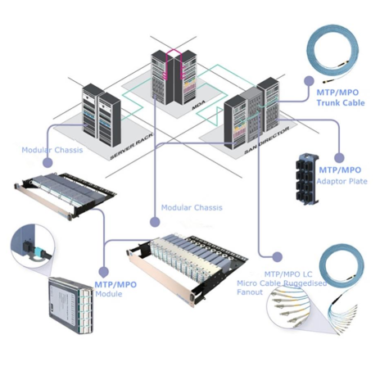
MPO Trunk Cable
An MPO trunk cable has an MPO connector at both ends. It provides a high-density connection between two distribution points.
Typical applications include:
- Connecting two fiber distribution panels
- Connecting MPO adapter panels
- Linking data center rows
- Building high-density backbone cabling
- Connecting modular cassettes
An MPO trunk may contain 8, 12, 16, 24 or more fibers.
MPO Breakout Cable
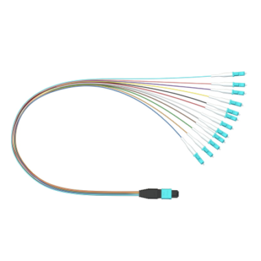
An MPO breakout cable has an MPO connector on one end and multiple individually jacketed fiber legs on the other end.
Depending on the design, the breakout side may be terminated with:
- LC connectors
- SC connectors
- FC connectors
- ST connectors
- Other equipment-specific interfaces
The term “breakout cable” is sometimes used broadly. The exact connector quantity and channel configuration should always be specified.
MPO-to-LC Breakout Cable
An MPO-to-LC breakout cable converts a multi-fiber MPO interface into individual LC channels.
Common configurations include:
- MPO-12 to 12 simplex LC connectors
- MPO-12 to 6 duplex LC connectors
- MPO-12 to 4 duplex LC connectors for 40G-to-10G breakout applications
- MPO-8 to 4 duplex LC connectors
- MPO-16 to 8 duplex LC connectors
The number of LC connectors does not always equal the nominal MPO fiber count. Some parallel-optics applications leave certain fiber positions unused.
How an MPO-12 Breakout Cable Supports 40G-to-10G Migration
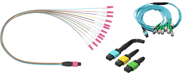
One of the best-known applications of an MPO-12 breakout cable is dividing a 40G QSFP+ SR4 interface into four independent 10G channels.
A 40GBASE-SR4 transceiver uses:
- Four transmit fibers
- Four receive fibers
- Eight active fibers in total
Although the connector may use an MPO-12 ferrule, the four center fiber positions are generally unused in this application.
The breakout assembly converts the MPO interface into four duplex LC connections. Each duplex LC pair can then connect to one 10G SFP+ transceiver.
This enables a single 40G QSFP+ port to communicate with four individual 10G SFP+ ports, provided that:
- The switch or server supports breakout operation.
- The transceiver types are compatible.
- The fiber type matches the transmission standard.
- The cable polarity is correct.
- The channel mapping follows the equipment requirements.
A passive breakout cable does not independently convert transmission speed. It only provides the required optical channel mapping. Breakout support must also be available in the connected equipment.
Major Benefits of MPO Cabling

1. Higher Connection Density
An MPO connector carries multiple fibers within a compact interface. This allows more optical channels to be installed within a limited rack, panel or pathway area.
Compared with installing the same number of individual LC or SC connectors, MPO cabling can:
- Reduce front-panel space
- Increase port density
- Reduce cable congestion
- Improve pathway utilization
- Simplify high-fiber-count connections
This is particularly valuable in hyperscale facilities, colocation data centers and telecommunications rooms where rack space is limited.
2. Faster Installation
MPO cables are normally pre-terminated, polished and tested before shipment.
Instead of terminating multiple individual connectors in the field, installers can connect a complete multi-fiber assembly using one MPO interface.
This can reduce:
- Field termination time
- Labor requirements
- Connector polishing work
- Installation inconsistencies
- On-site testing complexity
Pre-terminated cabling is especially useful in projects with short deployment schedules or repeatable rack designs.
3. Simplified Backbone Cabling
MPO trunk cables can consolidate multiple fiber channels into fewer cable assemblies.
For example, a high-density MPO trunk may connect two distribution panels, while MPO-to-LC cassettes convert the backbone fibers into standard duplex LC ports at each end.
This modular design separates the backbone cabling from the equipment interface. Equipment-side connectivity can then be changed without necessarily replacing the entire trunk.
4. Support for Parallel-Optics Transmission
Many high-speed multimode optical standards transmit data over several fibers simultaneously.
Parallel-optics transceivers may assign multiple fibers to separate transmit and receive lanes. MPO connectors provide a compact method of connecting these channels within one interface.
Depending on the transceiver and standard, MPO assemblies may be used with:
- 40G SR4
- 100G SR4
- 100G SR10
- 400G SR8
- Other parallel-optics applications
Fiber count and lane assignment vary by transceiver. The cabling configuration should therefore be verified against the equipment manufacturer’s specifications.
5. Flexible Migration Between Network Speeds
MPO-based cabling can support several migration strategies.
A data center may use:
- MPO trunks with LC cassettes for duplex applications
- MPO-to-LC breakout cables for channel separation
- Direct MPO-to-MPO connections for parallel optics
- Conversion modules to reorganize fiber lanes
- Higher-fiber-count trunks for multiple equipment generations
This flexibility can reduce disruption during network upgrades. However, successful migration still depends on fiber type, connector format, polarity and transceiver compatibility.
MPO cabling should therefore be described as migration-ready, rather than universally future-proof.
6. Improved Cable Management
Replacing many individual patch cords with a smaller number of MPO assemblies can make fiber pathways easier to organize.
Potential benefits include:
- Fewer cable bundles
- Cleaner rack layouts
- Reduced congestion
- Easier identification
- Improved airflow around active equipment
- More efficient moves, additions and changes
Proper labeling remains essential because one MPO connector may carry several independent optical channels.
7. Consistent Factory-Terminated Performance
Factory-terminated MPO assemblies can be produced under controlled polishing, inspection and testing conditions.
Depending on the product specification, testing may include:
- Insertion loss
- Return loss
- End-face inspection
- Polarity verification
- Fiber continuity
- Channel mapping
- Interferometer geometry inspection
Low-loss MPO assemblies may be required when a link includes several mated connector pairs, cassettes or distribution modules.
8. Potentially Lower Installed Cost
MPO cabling is not always less expensive on a per-connector basis. Its economic advantage is more accurately evaluated through total installed cost.
Cost savings may result from:
- Reduced installation labor
- Faster deployment
- Less field termination
- Higher panel density
- Fewer cable assemblies
- Simplified backbone installation
- Easier future reconfiguration
The actual cost depends on the network design, product quality, link-loss budget and number of conversion components.
Applications of MPO Cabling in Modern Data Centers
High-Density Backbone Connections
MPO trunk cables are frequently used between main distribution areas, horizontal distribution areas and equipment distribution areas.
They allow multiple fiber channels to be routed efficiently between cabinets or data center zones.
Spine-and-Leaf Networks
Spine-and-leaf architectures require a large number of connections between switching layers. MPO cabling can help manage the high fiber counts associated with these architectures.
Top-of-Rack and Middle-of-Row Designs
MPO-to-LC breakout cables can connect high-density switch ports to servers, storage systems or existing LC-based equipment.
This is useful when the backbone uses MPO connectivity but the equipment still uses duplex LC interfaces.
Parallel-Optics Transceiver Connections
Direct MPO-to-MPO cables are used to connect compatible parallel-optics transceivers.
The fiber count, polarity and connector gender must match the transceiver requirements.
Modular Patch Panels and Cassettes
MPO cassettes convert MPO trunk connections into LC or SC ports. This approach provides familiar equipment-side interfaces while maintaining a high-density backbone.
Storage Area Networks
MPO cabling can also support high-density connections in storage area networks, particularly where multiple duplex channels must be routed between switching and storage equipment.
MPO Polarity Methods
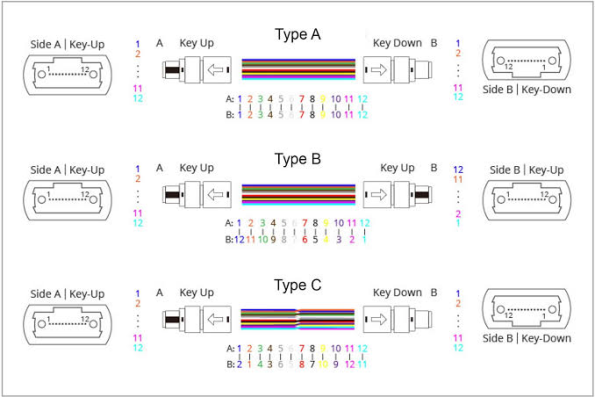
Polarity defines how transmit fibers at one end of a link are connected to receive fibers at the opposite end.
The three commonly referenced MPO polarity methods are:
Method A
Method A uses a straight-through fiber sequence. Position 1 at one end connects to position 1 at the opposite end.
Additional polarity management is required elsewhere in the link to create the necessary transmit-to-receive crossover.
Method B
Method B reverses the complete fiber sequence. Position 1 connects to the highest-numbered position at the opposite end.
This method is frequently used in parallel-optics connections.
Method C
Method C swaps adjacent fiber pairs. Position 1 connects to position 2, position 2 connects to position 1 and so on.
It is generally associated with certain duplex channel applications.
The correct method depends on the complete channel design, including trunks, adapters, cassettes, patch cords and transceivers. Components from different polarity systems should not be mixed without confirming the resulting fiber mapping.
MPO Connector Gender and Key Orientation
MPO connectors may be:
- Male, with guide pins
- Female, without guide pins
A proper mated connection normally requires one male connector and one female connector. Two male connectors should not be mated because their guide pins interfere with each other. Two female connectors may physically meet, but alignment will not be properly controlled.
MPO connectors also use key-up and key-down orientation. Key orientation affects polarity and fiber-position mapping.
Connector gender and key orientation should therefore be specified separately from the fiber count.
UPC and APC MPO Connectors
MPO connectors may use different end-face geometries.
MPO UPC
MPO UPC connectors are commonly used with multimode fibers and some single-mode applications. They are generally identified by a flat or slightly angled polished multi-fiber ferrule, depending on the connector specification.
MPO APC
Single-mode MPO connectors commonly use an angled physical-contact end face to improve return-loss performance.
MPO UPC and MPO APC connectors should not be directly mated. Their ferrule geometries are different and incompatible mating can cause excessive insertion loss or connector damage.
How to Select the Right MPO Cable
Consider the following factors before ordering an MPO cable assembly.
| Selection Factor | Questions to Confirm |
|---|---|
| Application | Is the cable used as a trunk, breakout, conversion or direct transceiver connection? |
| Fiber count | Does the equipment require 8, 12, 16, 24 or another fiber count? |
| Fiber type | Is OS2, OM3, OM4 or OM5 required? |
| Connector gender | Should each end be male or female? |
| Key orientation | Is key-up to key-up or key-up to key-down required? |
| Polarity | Does the channel require Method A, Method B, Method C or a customized mapping? |
| End-face type | Is UPC or APC required? |
| Insertion loss | Does the link-loss budget require standard-loss or low-loss connectors? |
| Breakout configuration | How many LC or SC connectors are required, and how should the channels be mapped? |
| Cable jacket | Is PVC, LSZH, OFNR, OFNP or another rating required? |
| Length | What trunk length and breakout-leg length are needed? |
| Pulling protection | Will the cable be installed through trays, conduits or raised floors? |
| Testing | Are insertion-loss, return-loss and polarity reports required? |
Common MPO Cabling Mistakes
Assuming Every MPO-12 Application Uses All 12 Fibers
Some MPO-12 applications use only eight active fibers. The number of active channels must be verified against the transceiver specification.
Selecting the Wrong Connector Gender
Connecting two pinned MPO connectors can damage the guide pins. Connector gender should be confirmed for every interface.
Mixing Polarity Methods
A trunk, cassette and patch cable may each be correctly manufactured but still create an incorrect channel if they belong to incompatible polarity systems.
Mating UPC and APC Connectors
Different end-face geometries should not be mixed.
Ignoring the Link-Loss Budget
Every connector pair, splice, cassette and conversion module adds insertion loss. A complete loss calculation should be performed before deployment.
Failing to Inspect and Clean Connectors
Because an MPO ferrule contains multiple fibers, one contaminated connector can affect several channels simultaneously.
Both connector end faces should be inspected and cleaned before mating.
Frequently Asked Questions
Is an MPO-12 cable always a 12-channel cable?
No. MPO-12 describes the ferrule position count. Some applications use all 12 fibers, while 40GBASE-SR4 and 100GBASE-SR4 normally use eight active fibers.
Can an MPO cable convert 40G into four 10G connections?
An MPO-to-LC breakout cable can separate the four optical lanes, but the connected switch and transceiver must support 4 × 10G breakout operation. The cable itself does not electronically convert the data rate.
Can MPO cabling be used for 400G?
Yes, but the required cable depends on the 400G transceiver type. Some interfaces use MPO-16, while others may use MPO-12, duplex LC or different connector formats.
Is OM4 always better than OM3?
OM4 supports a higher modal bandwidth and may provide longer transmission distances for some applications. However, the correct choice depends on link length, transceiver specification, existing infrastructure and budget.
Are MPO and MTP connectors compatible?
MTP connectors are designed to comply with the MPO interface. They may be mated with compatible MPO connectors when fiber count, gender, key orientation, polarity and end-face specifications match.
Conclusion
MPO cabling provides an efficient method of supporting high-density and high-speed optical networks. By combining multiple fibers within a compact connector, MPO assemblies can reduce cable congestion, accelerate installation and support both duplex and parallel-optics architectures.
MPO-12 breakout cables and MPO-to-LC breakout cables are particularly useful for connecting high-density backbone systems to LC-based equipment and for supporting compatible 40G-to-10G or 100G-to-25G breakout applications.
However, MPO products are not universally interchangeable. Fiber count, polarity, connector gender, key orientation, end-face type, fiber category and insertion-loss requirements must all be verified before installation.
Fiber-Life supplies configurable MPO and MTP cable assemblies, including trunk cables, breakout cables, MPO-to-LC harnesses and high-fiber-count solutions. Fiber type, connector gender, polarity, cable length, jacket material, breakout configuration and testing requirements can be customized for data center, telecommunications and enterprise-network applications.