FREE SHIPPING On Orders Over US$200
Why a 7.5-Millimeter Bend Radius Is Worth a 150% Price Premium
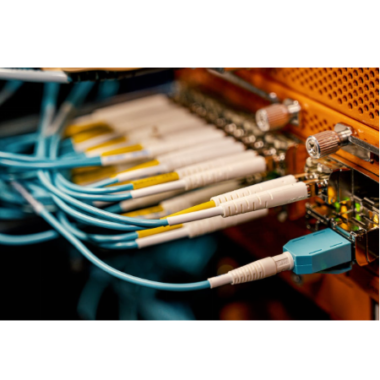
It was supposed to be a routine turn-up. A hyperscale data center technician routed a new 100G link between two switches in adjacent racks. The fiber path was clean—eight meters of OS2 single-mode, LC connectors, tested at the factory. But the link would not stabilize. Bit errors spiked every afternoon, then cleared overnight. After three days of troubleshooting transceivers, patch panels, and switch ports, the culprit was found: a 90-degree bend in the cable management duct, radius approximately 12 mm, where the fiber had been forced around a power cable tray. Standard G.652.D fiber is rated for 30 mm minimum bend radius. At 12 mm, the macro-bending loss at 1550 nm exceeded 3 dB—enough to push the coherent receiver below its OSNR threshold.
The fix? Replace the cable with G.657.A2 bend-insensitive fiber, rated for 7.5 mm bends with <0.03 dB loss.
Problem solved. But the three-day outage cost $47,000 in lost SLA credits.
This is the reality of fiber optic cabling in 2026. The glass itself is a marvel of materials science, but the cable is only as good as the engineering decisions made around it—bend radius, jacket material, connector polish, and fiber grade. This guide moves beyond “light bouncing in a tube” and treats the fiber cable as a precision waveguide system with hard physical limits.
Part I: How Fiber Actually Works—Beyond the “Bouncing Light” Myth
The Waveguide Reality
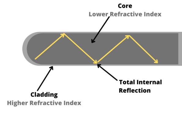
Most explanations of fiber optics describe light “bouncing” inside the core like a ball in a pipe. This is wrong. Optical fiber is a dielectric waveguide. Light does not reflect off the core-cladding boundary like a mirror; it propagates as confined electromagnetic modes whose energy is concentrated in the core but extends into the cladding as an evanescent field.
The core has a slightly higher refractive index than the cladding (Δn ≈ 0.36% for standard SMF). When light is launched within the acceptance cone defined by the numerical aperture (NA ≈ 0.14 for SMF), the waveguide conditions are satisfied and the energy remains guided. For single-mode fiber, only the fundamental LP₀₁ mode propagates. For multimode fiber, hundreds of modes can coexist, each traveling at a slightly different effective velocity.
Engineering Insight: The “bouncing light” analogy fails because it implies discrete reflections. In reality, the guided mode is a continuous standing wave pattern. The evanescent tail in the cladding is not “leaked” light—it is a required component of the mode structure. When you bend the fiber too sharply, this tail encounters the cladding-air boundary, couples into radiative modes, and escapes. That is macro-bending loss.
Total Internal Reflection—The Real Physics
Total internal reflection (TIR) occurs when light strikes the core-cladding interface at an angle greater than the critical angle:
θc = arcsin(n₂/n₁)
Where n₁ ≈ 1.467 (core) and n₂ ≈ 1.462 (cladding), giving θc ≈ 85.2°. But TIR alone does not explain single-mode operation. The fiber’s normalized frequency (V-number) determines how many modes are supported:
V = (2πa/λ) · NA
For a standard single-mode fiber with core radius a = 4.25 µm, NA = 0.14, and λ = 1310 nm, V ≈ 2.3. Single-mode propagation requires V < 2.405. At 1550 nm, V drops to ~1.9, ensuring single-mode operation across the entire telecom window.
Attenuation: Where the Photons Go
Even in pristine silica, photons disappear. The three primary loss mechanisms are:
- Rayleigh Scattering: Caused by microscopic density fluctuations frozen into the glass during manufacturing. Scales as λ⁻⁴. This is why 1550 nm has lower attenuation (~0.20 dB/km) than 1310 nm (~0.35 dB/km). It is the fundamental floor—no fiber can go below it.
- Infrared Absorption: Vibrational resonances of Si-O bonds absorb beyond 1600 nm. This defines the long-wavelength boundary of telecom fibers.
- OH⁻ Ion Absorption: Water molecules trapped in the glass create absorption peaks at 1383 nm. Legacy G.652.A/B fibers had a “water peak” here, rendering the E-band unusable. Modern G.652.D and G.657 fibers eliminate this through dehydration processing, opening the full 1260–1625 nm window.
Part II: The Anatomy of a Fiber Cable—From Photon to Polymer
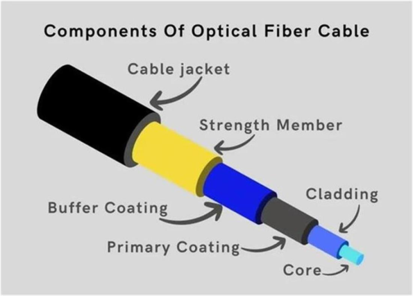
A fiber optic cable is not “a piece of glass.” It is a multi-layer precision assembly where each layer solves a specific engineering problem.
The Core and Cladding: A Single Piece of Glass
The core (9 µm for SMF, 50/62.5 µm for MMF) and cladding (125 µm) are manufactured as a single draw from a preform. They cannot separate. The refractive index profile is created by doping the core with germanium dioxide (GeO₂), raising its index slightly above pure silica cladding.
Critical Detail: The 125 µm cladding diameter is standardized to ±0.7 µm across all telecom fibers globally. This precision is what allows any two fibers to be fusion-spliced with <0.05 dB loss, regardless of manufacturer.
The Coating: Where Most Failures Begin
Immediately after drawing, the bare glass is coated with a dual-layer polymer:
- Inner layer (soft): Low-modulus acrylate that cushions micro-bending
- Outer layer (hard): High-modulus acrylate that protects against abrasion
Total coating diameter: 242 µm (standard) or 200 µm (thin-coat for high-density cables). The coating is the primary moisture barrier. If it delaminates or is nicked during stripping, water ingress will create stress corrosion at the glass surface, leading to static fatigue—slow crack growth that causes failure months or years later.
Buffer, Strength Members, and Jacket
| Layer | Function | Materials | Key Spec |
|---|---|---|---|
| Tight buffer | Mechanical protection for indoor cables | 900 µm PVC or LSZH | Direct connector termination |
| Loose tube | Allows fiber to move within gel-filled tube | HDPE + thixotropic gel | Outdoor temperature range |
| Strength members | Absorbs pulling tension | Aramid yarn (Kevlar), FRP, steel | Tensile rating: 100–1,500 N |
| Inner jacket | Bundling and secondary protection | PE, LSZH, PVC | Crush resistance: 500–2,000 N/cm |
| Armor | Rodent/crush protection | Corrugated steel, interlocked aluminum | Impact resistance |
| Outer jacket | Environmental barrier | PE (outdoor), LSZH (indoor), TPU (industrial) | UV resistance, flame rating |
Part III: Single-Mode Fiber—The Long-Haul Precision Instrument
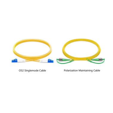
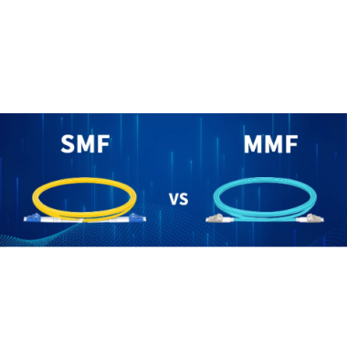
Single-mode fiber (SMF) dominates modern networks because it eliminates modal dispersion, enabling coherent transmission at 400G/800G over thousands of kilometers. But “single-mode” is not a monolith.
G.652.D: The Global Workhorse
ITU-T G.652.D is the most widely deployed fiber on Earth, accounting for over 70% of installed fiber in metro and long-haul networks.
| Parameter | G.652.D Specification |
|---|---|
| Core/Cladding | 9/125 µm |
| Mode Field Diameter | 9.2 ± 0.4 µm @ 1310 nm |
| Attenuation | ≤0.35 dB/km @ 1310 nm; ≤0.20 dB/km @ 1550 nm |
| Chromatic Dispersion | 0–3.5 ps/nm·km @ 1310 nm; 15–18 ps/nm·km @ 1550 nm |
| Min Bend Radius | 30 mm |
| Wavelength Range | 1260–1625 nm (zero water peak) |
G.652.D is the default choice for backbone, FTTH distribution, and any link where routing is controlled and bending is not extreme. But its 30 mm bend limit is a liability in high-density environments.
G.657.A1/A2: Bend-Insensitive Revolution
Bend-insensitive fiber (BIF) solves the macro-bending problem through a trench-assisted refractive index profile. A low-index “trench” is added around the core, creating a potential well that traps the evanescent field more tightly. Even when bent to small radii, the mode remains confined.
| Parameter | G.657.A1 | G.657.A2 |
|---|---|---|
| Min Bend Radius | 10 mm | 7.5 mm |
| Macrobending Loss @ 1550 nm, 10 mm radius | ≤0.25 dB | ≤0.03 dB |
| Compatibility | Fully compatible with G.652.D | Fully compatible with G.652.D |
| Typical Premium vs G.652.D | ~30% | ~150% |
| Best For | FTTH drops, MDU wiring | AI data centers, dense patch panels |
Why the 2026 Surge in G.657.A2 Demand: AI data centers require 5–10× more fiber than traditional facilities. A single GPU cluster routes thousands of patch cords through tight cable management. Global data center fiber demand reached 69.6 million core-km in 2025 and is projected to exceed 100 million in 2026.
G.657.A2 is becoming the de facto standard for high-density patching.
Splicing Note: G.657.A1/A2 are fully backward-compatible with G.652.D. Fusion splicing between the two produces negligible additional loss because their mode field diameters match.
When NOT to Use Bend-Insensitive Fiber
G.657.A2 is not universally superior. In straight, well-managed backbone runs, the premium is wasted. Worse, some G.657 variants (particularly G.657.B3 with 5 mm bend radius) are not fully compatible with G.652.D and can cause elevated splice loss. Always specify G.657.A2 (not B3) for mixed infrastructure.
Part IV: Multimode Fiber—The Short-Distance Workhorse
Multimode fiber (MMF) supports multiple propagation modes, creating modal dispersion that limits bandwidth-distance product. But for short links, MMF paired with low-cost VCSELs remains unbeatable.
The OM Hierarchy: A Complete Technical Comparison
| Standard | Core | 850 nm BW | 1300 nm BW | 10G Reach | 40/100G Reach | Laser Optimized | Jacket Color |
|---|---|---|---|---|---|---|---|
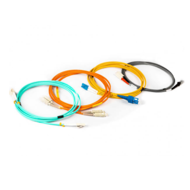
| OM1 | 62.5 µm | 200 MHz·km | 500 MHz·km | 33 m | Unsupported | No | Orange |
| OM2 | 50 µm | 500 MHz·km | 500 MHz·km | 82 m | Unsupported | No | Orange |
| OM3 | 50 µm | 2,000 MHz·km | 500 MHz·km | 300 m | 100 m | Yes (VCSEL) | Aqua |
| OM4 | 50 µm | 4,700 MHz·km | 500 MHz·km | 550 m | 150 m | Yes (VCSEL) | Aqua |
| OM5 | 50 µm | 4,700 MHz·km | 500 MHz·km | 550 m | 150 m | Yes (SWDM4) | Lime Green |
OM5 is not “faster OM4.” It is engineered for Short-Wavelength Division Multiplexing (SWDM), carrying four wavelengths (850/880/910/940 nm) simultaneously over a single fiber. This quadruples capacity without adding fibers—critical for parallel optics in data centers.
The 62.5 µm Trap: OM1’s 62.5 µm core was designed for LED sources in the 1990s. Modern VCSELs are optimized for 50 µm cores. Connecting OM1 to OM3/OM4 equipment creates a mode-field mismatch that can add 2–4 dB loss. Never mix 62.5 µm and 50 µm fibers in the same link.
Part V: Cable Construction—Matching the Environment
Loose-Tube vs. Tight-Buffer
| Feature | Loose-Tube | Tight-Buffer |
|---|---|---|
| Construction | Fibers float in gel-filled HDPE tubes | 900 µm PVC/LSZH directly over fiber |
| Temperature range | −40°C to +70°C | −20°C to +60°C |
| Bend radius | 10× cable OD | 10× cable OD |
| Best for | Outdoor, long-haul, duct/conduit | Indoor, patch cords, premises cabling |
| Termination | Requires splice to pigtail | Direct connector termination |
Jacket Ratings: The Fire Safety Hierarchy
| Rating | Full Name | Flame Test | Use Case |
|---|---|---|---|
| OFNP | Optical Fiber Nonconductive Plenum | UL 910 (Steiner tunnel) | Air handling spaces (HVAC plenums) |
| OFNR | Optical Fiber Nonconductive Riser | UL 1666 (Riser flame) | Vertical shafts between floors |
| LSZH | Low Smoke Zero Halogen | IEC 60332-3 | Indoor general use, ships, subways |
| PVC | Polyvinyl Chloride | None (general indoor) | Non-critical indoor environments |
| PE | Polyethylene | None | Outdoor, UV-resistant, direct burial |
Critical Detail: Never route outdoor PE-jacketed cable indoors beyond the permitted transition point (typically 50 feet or 15 meters per NEC 770). PE burns rapidly and releases dense smoke. The transition to indoor-rated cable must occur at the building entry point.
Armored Cable
Armored fiber uses corrugated steel or interlocked aluminum to protect against:
- Rodent damage: Rats and squirrels can chew through standard jackets
- Crush loads: Direct burial or under-road installations
- Abrasion: Dragging over rough surfaces during installation
But armor adds weight (2–5× standard cable), reduces flexibility, and must be grounded at one end only to prevent ground loops. In all-dielectric installations (e.g., near high-voltage power lines), specify non-metallic armor (aramid-reinforced or FRP).
Part VI: Connectors, Polish, and the Polarity Trap
Connector Types by Application
| Connector | Ferrule | Latch | Best For | Density |
|---|---|---|---|---|
| LC | 1.25 mm ceramic | Push-pull | SFP/QSFP, high-density patching | 144 ports/RU |
| SC | 2.5 mm ceramic | Snap-in | Telecom ODFs, FTTH, PON | 72 ports/RU |
| FC | 2.5 mm metal | Threaded | Industrial, test equipment, vibration zones | Low |
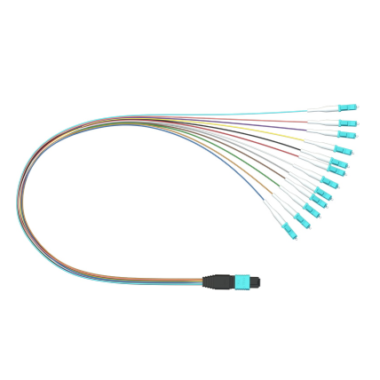
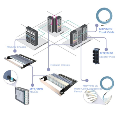
| MPO/MTP | 2.5×6.4 mm composite | Push-pull | 40G/100G/400G parallel optics | 8–32 fibers/connector |
UPC vs. APC: A Physics Decision
| Polish | End Face | Return Loss | Reflection | Use Case |
|---|---|---|---|---|
| UPC | Domed, 0° | ≥ 50 dB | ~0.001% | Digital Ethernet, data centers |
| APC | Domed, 8° | ≥ 60 dB | ~0.0001% | PON, CATV, DWDM, coherent optics |
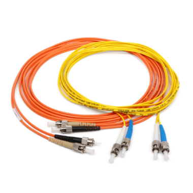
APC connectors are mandatory in PON networks (GPON/XGS-PON) because back-reflection from UPC interfaces (−14 dB typical) interferes with WDM filters and raises laser noise. The 8° angle reflects stray light into the cladding, where it is absorbed. APC connectors are color-coded green; UPC is blue (SM) or beige/aqua (MM). Never mate APC to UPC—it creates an air gap, >3 dB loss, and ferrule damage.
MPO Polarity: The Silent Killer
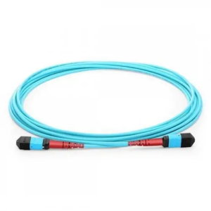
MPO cables have three polarity methods (A, B, C). A Method A trunk patched with a Method B harness flips Tx/Rx pairs, creating a loopback that optical power meters will not catch. Always verify polarity with a channel tester or visual fault locator before declaring a parallel-optics link “good.”
Part VII: Emerging Applications—Where Fiber Is Heading in 2026
AI Data Centers: The G.657.A2 Explosion
AI clusters require massive east-west bandwidth between GPUs. A single NVIDIA DGX system can consume 400G per link, and training clusters span thousands of nodes. This drives unprecedented fiber density. G.657.A2’s 7.5 mm bend radius allows patch cords to be routed through impossibly tight cable managers without the micro-bending losses that plague G.652.D.
FTTR: Fiber to the Room
In multi-dwelling units (MDUs) and hotels, FTTR extends fiber from the basement OLT to individual rooms, replacing copper Ethernet. G.657.A2 drop cables navigate tight wall corners and small terminal boxes where G.652.D would fail.
Co-Packaged Optics (CPO)
As switch ASICs push beyond 51.2 Tbps, electrical traces on PCBs become the bottleneck. Co-packaged optics place optical engines directly on the switch chip package, eliminating copper traces. This requires ultra-short, ultra-dense fiber assemblies—often G.657.A2 or even G.657.B3—routed within millimeters of the chip.
Part VIII: Selection Framework—The Six-Step Decision Tree
Step 1: Define Distance and Data Rate
- < 100 m, 10G–100G: OM4/OM5 multimode with VCSELs (lowest cost)
- 100 m–2 km, 10G–400G: OS2 single-mode, G.652.D or G.657.A2
- > 2 km, any rate: OS2 single-mode exclusively
- > 80 km: OS2 with DWDM amplification
Step 2: Assess Bending Constraints
- Controlled routing (conduit, tray): G.652.D (cost-optimized)
- High-density patching, FTTH drops, MDU: G.657.A1
- AI data centers, tight cable managers, micro-ducts: G.657.A2
Step 3: Choose Cable Construction
| Environment | Cable Type | Fiber | Jacket |
|---|---|---|---|
| Indoor plenum | Tight-buffer | OS2/OM4 | OFNP/LSZH |
| Indoor riser | Tight-buffer | OS2/OM4 | OFNR/LSZH |
| Outdoor duct | Loose-tube | OS2 G.657.A2 | PE, gel-filled |
| Direct burial | Loose-tube armored | OS2 | PE + steel armor |
| Aerial | ADSS/figure-8 | OS2 | PE, UV-resistant |
| Industrial | Armored tight-buffer | OS2 | TPU, metal-braid |
Step 4: Match Connector to Equipment
- SFP/QSFP/QSFP-DD: LC duplex
- Telecom ODF/FTTH: SC/APC for PON, SC/UPC for Ethernet
- 40G/100G/400G parallel optics: MPO-12 or MPO-16
- Vibration-prone industrial: FC/APC
Step 5: Specify Polish Type
- Digital systems only: UPC (blue/beige)
- PON, CATV, DWDM, coherent: APC (green)
- When in doubt: APC—UPC adapters cannot accept APC, but APC adapters can physically accept UPC (though performance degrades)
Step 6: Verify Certification and Testing
Insist on:
- Insertion loss and return loss per connector
- 3D interferometry for ferrule geometry
- OTDR traces for installed links
- TIA-568.3-D or ISO/IEC 14763-3 compliance
Part IX: The Seven Deadly Sins of Fiber Installation
- Violating Bend Radius A 30 mm minimum means 30 mm under load. A cable tied with a zip-tight cable tie to a 30 mm radius post creates a 15 mm effective bend under tension. Use bend-radius guides and velcro straps.
- Mixing APC and UPC The 8° angle on APC creates an air gap against flat UPC, producing >3 dB loss and chipping ferrules. Both connectors are destroyed.
- Routing Outdoor Cable Indoors PE jacketed cable routed through a plenum space violates fire code and invalidates insurance. Transition to OFNP/LSZH at the building entry.
- Ignoring the Water Peak On legacy G.652.A/B fiber, the 1383 nm water peak adds ~0.5 dB/km. If your CWDM plan includes 1391 nm, test the fiber with an OTDR first.
- Skipping End-Face Inspection A 5 µm dust particle on the core can add 1–5 dB loss. Always inspect at 200–400× before mating. IEC 61300-3-35 defines pass/fail criteria.
- Over-Tension During Pull Exceeding the cable’s tensile rating (typically 600 N for indoor, 1,500 N for outdoor) stretches the fiber, creating micro-cracks that cause future failure. Use proper pulling grips and never pull by the jacket alone.
- The “Good Enough” Procurement Trap A $0.50/meter cable from an unverified supplier may use recycled preforms with inconsistent index profiles. In a 10 km link, this creates splice-point ghosts and PMD spikes that take days to diagnose. Specify Corning, Prysmian, YOFC, or equivalent Tier-1 fiber.
FAQ: Deep-Dive Answers
Q: Can I mix G.652.D and G.657.A2 in the same link?
A: Yes. G.657.A1/A2 are fully backward-compatible with G.652.D. Fusion splicing produces negligible additional loss. Use G.657.A2 only in the bend-critical sections (patch cords, drops) and G.652.D in the backbone to optimize cost.
Q: Is OM5 worth the premium over OM4?
A: Only if you are deploying SWDM4 transceivers (e.g., 100G-SWDM4) that use four wavelengths over a single fiber. For standard 10G/25G/40G SR optics, OM4 performs identically at lower cost.
Q: Why does my OTDR show a “ghost” reflection at 2 km?
A: OTDR ghosts are caused by strong reflections (typically from APC connectors or unterminated fibers) creating secondary pulses. They appear at exact multiples of the real reflection distance. Use index-matching gel or verify with a bi-directional OTDR test.
Q: Can I use multimode fiber for 100G?
A: Yes, but only for short distances. 100G-SR10 over OM4 supports 100 m. For links beyond 150 m, single-mode is mandatory. Do not attempt to “stretch” MMF beyond its rated reach—the BER will degrade unpredictably.
Q: What is the actual lifespan of fiber cable?
A: Properly installed fiber has a design life of 25–40 years. The glass itself does not degrade. Failures are almost always mechanical (bend, crush, tension) or at connectors (contamination, wear). The cable often outlives the active equipment it connects.
Summary: Fiber Is Not a Commodity
The fiber optic cable is the longest-lived component in your network infrastructure. Switches last 5–7 years. Transceivers last 3–5 years. Fiber, properly specified and installed, lasts decades. This makes the initial specification decision the highest-leverage engineering choice you will make.
Choosing G.652.D over G.657.A2 in a dense data center creates a latent failure mode that manifests only when a technician routes a cable too tightly. Choosing OM1 instead of OM4 kills your 10G upgrade path. Choosing PE jacket for an indoor run creates a fire code violation. These are not theoretical risks—they are field-proven failure patterns.
Understand the physics. Respect the bend radius. Match the fiber grade to the application. And treat the cable not as a commodity, but as a precision waveguide system that will carry your data for the next quarter-century.
Need fiber cables engineered for your specific link budget, bend constraints, or environmental envelope? Custom configurations from Fiber-Life—including G.657.A2 high-density assemblies, armored industrial cables, MPO polarity-managed trunks, and pre-terminated LSZH plenum-rated solutions—ensure your physical layer performs like your network design intends.